the Crown and QSC amps do use a center tapped transformer. the center tap is left floating, and the rails are driven, which the return of the power supply follows and provides the output to the speaker. the output devices are connected between the supply rails and ground, and "walk" the supply rails with the audio. it's a half bridge amp, just as a standard class B is, except the transistors drive the "other half" of the bridge (the power supply) rather than driving the speaker directly.
it's very similar to the principal of the "circlotron" amp, but in solid state form.
the other option would be to operate the transformers using a capacitive or resistive (or active) divider to create a ground return. generally, you could build a crown-like amp without a center tap on the transformer, and the power supply filter caps, not only would serve to couple the signal to the speaker, but also provide a capacitive divider and so a "center line" for the power supply. it would definitely be worth investigating, since it would simplify the power supply a little bit.
the "active" divider option would be the equivalent to a high power version of the opamp "battery splitter" used in guitar effects boxes to create split 4.5V rails from a 9V battery, but your "opamp" would actually be a power amp and a voltage divider at the input to provide a low impedance virtual ground.
You can lift the circuit from the Quad amplifiers:
http://www.diyaudio.com/forums/showthread.php?postid=1141706#post1141706
To be on the safe side, use somewhat larger components.
http://www.diyaudio.com/forums/showthread.php?postid=1141706#post1141706
To be on the safe side, use somewhat larger components.
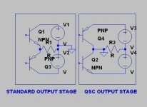
i've posted this jpg before (probably about 2 yrs ago....). it shows how the qsc and crown output stage works...
if you notice, the only thing that's been moved is the power supply and ground. the emitters still drive the load (this time through the power supply). one advantage to this is that the drivers and outputs can be driven with an op amp operating from +/-12V without the use of a VAS operating from high rail voltages. the only thing really required for full output is a lot of current gain. the voltage gain actually is developed by the output stage and the floating output rails.
if you notice, the only thing that's been moved is the power supply and ground. the emitters still drive the load (this time through the power supply). one advantage to this is that the drivers and outputs can be driven with an op amp operating from +/-12V without the use of a VAS operating from high rail voltages. the only thing really required for full output is a lot of current gain. the voltage gain actually is developed by the output stage and the floating output rails.
Attachments
Bernhard,
in case you wanted to build something active to get a "virtual ground", then consider taking this just a little bit further and build a true bridge amp. "GND" then carries no spkr-load currents and is only a reference potential. Many of eg Nelson Pass designs qualify.
@Uncle: I wouldn't label the QSC schemes (both with and without ctr tap) a cirlotron, but that's of course a semantics question. IHMO, it's a plain single-ended design, exept that the OS is cleverly split up, or "wrapped inside out", so to say. However, it still is, the classic "passive bridge" topology, either with a DC path or without (the latter case with DC blocking in the input to prevent static imbalance/runaway).
- Klaus
The Crown and QSC output stages are not the same.
Crown use what they call a 'grounded bridge' configuration which is described here: http://www.crownaudio.com/pdf/amps/grbgpapr.pdf There are two sets of output devices and a single rail supply.
QSC just use a very common rearrangement of a standard push-pull output stage to allow the output devices to be electrically connected to a grounded heatsink. This has many benefits, especially heat conduction from the transistors to the heatsink.
The Crown and QSC are related to each other. The "high side" of a Crown grounded bridge is a normal run-of-the-mill amplifier. The "low side" of the Crown which generates the virtual ground is essentially a QSC amp (with darlington outputs instead of CFPs, but the operating principle is the same). They couple together through the power supply.
Bernhard said:Thanks everybody, I liked very much the looks of the aluminum potted transformers of the Pioneer A-878 amps
It's good that you like them, because any of these potential amp topologies really require a separate trafo for each channel. make sure the chassis is heavy enough to handle it
.Crown grounded bridge requires one trafo (or at least isolated windings) per channel, and requires no center tap. The QSC also requires isolated supplies, and can be built without the center tap. The QSC class H varieties require center taps, but the basic transnova circuit does not need it. Thier old circuits just used two caps (and didn't even bother with the equalization resistors).
- Status
- This old topic is closed. If you want to reopen this topic, contact a moderator using the "Report Post" button.
- Home
- Amplifiers
- Solid State
- Virtual Ground ?