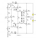
Figure 1 (below, second post) shows a section of the
AV800 amplifier where the predrivers
stages get their power from the
+90v and -90v power supply via
the 100 ohm resistor/diode network
and 220uf capactor (D8, R17, C2).
Question:
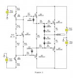
Figure 2 (below, 3rd post) shows the predriver stage
being powered by a seperate
power source that is also +90v and
-90v.
Is figure 2 a valid design method?
When the output stage drives,
the large transformer supplying
+90v/-90v will sag down to rms
value under severe load, perhaps
as low as 65 - 70 volts. Can the
predrive stage operate at a constant
+90v volts *and* the output stage
operate at 65v under load ? Will
the voltage mismatch cause problems?
Av800 schematic
http://www.aussieamplifiers.com/downloads/AV800.pdf
AV800 amplifier where the predrivers
stages get their power from the
+90v and -90v power supply via
the 100 ohm resistor/diode network
and 220uf capactor (D8, R17, C2).
Question:
Figure 2 (below, 3rd post) shows the predriver stage
being powered by a seperate
power source that is also +90v and
-90v.
Is figure 2 a valid design method?
When the output stage drives,
the large transformer supplying
+90v/-90v will sag down to rms
value under severe load, perhaps
as low as 65 - 70 volts. Can the
predrive stage operate at a constant
+90v volts *and* the output stage
operate at 65v under load ? Will
the voltage mismatch cause problems?
Av800 schematic
http://www.aussieamplifiers.com/downloads/AV800.pdf

Two rails
10 Print ''Hi, hear you !!"
20 End !!!
Hi,
I have used a similar scheme with separate supplies for the two stages. In my case I used 'separately' derived supplies.
I had no problems and never blew any transistors. However, the higher supply of the driver would pull the base of the OP trs above their supply voltage. This would happen when you clip. I don't remember what the waveform looks like under clipping conditions or the recovery waveforms. But the bottom line was that the amp sounded very good and I did play it clipped at times without any fireworks or disgusting sounds.
I am building a new amp with this (powersupply) scheme. If you are interested I can post the results.
Cheers.
If you wanted to you, could just make C1 and C2 much much bigger, so whenever the main rails dipped a bit the pre-driver rails would stay put for a sufficiently long time. Diodes D7 and D8 allow the main rails to go lower momentarily without sucking the voltage out of C1 and C2 at the same time.
Circlotron said:If you wanted to you, could just make C1 and C2 much much bigger, so whenever the main rails dipped a bit the pre-driver rails would stay put for a sufficiently long time. Diodes D7 and D8 allow the main rails to go lower momentarily without sucking the voltage out of C1 and C2 at the same time.
Would too much capacitance at
C1 and C2 cause problems, lets
say I put 5,000 uf - 10,000 uf
on each predriver rail ?
jam said:I would run the front end off 100v rails. You are loosing about 8v per rail. This would raise the output of amplifier before clip.
Regards,
Jam
Cool, thanks for the tip. I'm not
an amp design guru, how do you
calculate the loss of 8v ?
You are saying that if I keep this
VAS stage at 100v with it's own
independent power supply
and connect the output stage
to the large power supply,
under load the output stage sags,
lets say down to 65v, clipping on the
output would be at ~100v not
~65v ?
Is this how it works?
Not quite. Provided the output devices bases can be driven far enough, the output will only ever clip at a bit less than the rails supplying it, no more. Maybe 5 volts or so less than the rail, depending on the amp. To clip at 100v you need to have at least +/- 100v supply rails at the point of clipping. This would be *some* amp BTW.thylantyr said:Is this how it works?
")
- Status
- This old topic is closed. If you want to reopen this topic, contact a moderator using the "Report Post" button.
- Home
- Amplifiers
- Solid State
- Amplifier Question - Predriver stages