Hi all.
Simulation file is in the .zip file I have uploaded. Models for the transistors are included in the netlist and you must use LTSpice.
I'm no expert, mostly because I don't have very much experience. However, I still like to contribute things like this every once in a while simply to socialize and also in the hope that others will find it educational. Knowledge is power. Maybe it's some teaching spirit showing through.
Anyways, you may be inclined towards skepticism upon seeing the figures, so to coax your curiosity here is Sander Sassen's ExtremeA, which uses the Allison output to great effect.
http://www.hardwareanalysis.com/content/article/1842.5/extrema-reference-class-a-diy-amplifier/
The distortion figures of this output stage neatly line up with the figures obtained from this ExtremA. So it is likely that the simulator is not spouting nonsense.
Also I believe some (many?) people do not know how to use LTSpice, the simulator I am using, correctly. When used correctly, the simulator can be a powerful friend, but only if used correctly. If someone is interested, I can compile a PDF detailing the proper use of LTSpice. Usually you can get questions answered quickly from the yahoo group anyways though.
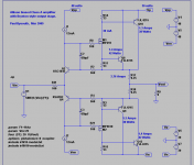
Here is the schematic:
All simulations are done at 34V pk-pk output, into an 8-ohm load. 36V rails.
Starting from the right in the schematic, going towards the left:
Circuit 1: Standard Allison
This is the normal Allison output stage. Despite all modifications, this version still has the lowest distortion.
THD @ 100Hz is .000120%
THD @ 20KHz is .000182%
Circuit 2: Allison with my modification, thus: Allison-Keane (not trying to unneedingly claim credit, but we might as well name it something. If it already has gone by some other name then I will happily release my title)
This modification allows one to use smaller emitter resistors, increasing maximum output power if you're using low bias current. It's useful for minimalist amplifiers for squeezing the most out of low supply voltages. Currently, it doesn't make much sense with such high bias current.
THD @ 100Hz is .000351%
THD @ 20KHz is .000528%
Circuit 3: Allison-Keane+Diamond
It may help your understanding of this circuit if you note that the additions have created two Rush Cascodes. As far as I know, I am the first to do it this way.
It cannot be innocently compared to circuit 2, since this version is not cascoded. However, it provides an indicator of the effect of cascoding if we compare it to circuit 4. We find that cascoding reduces distortion.
The main advantage of this circuit is it's rather high input impedance. This lowers distortion by loading the VAS less. This means that the distortion will increase less when the power level increases, and that you can set open-loop gain lower which will make the circuit more stable.
THD @ 100Hz is .000256%
THD @ 20KHz is .000292%
Circuit 4: Cascoded Allison-Keane+Diamond
This version of Circuit 2 serves to point out the effect of cascoding.
THD @ 100Hz is .000169%
THD @ 20KHz is .000222%
Afterword:
This is great and all, but if you actually want to give it justice in a proper amplifier, you will need to hook it up with a really good VAS. Good luck.
I hope this has been helpful and educational to viewers.
Bonzai,
- keantoken
Simulation file is in the .zip file I have uploaded. Models for the transistors are included in the netlist and you must use LTSpice.
I'm no expert, mostly because I don't have very much experience. However, I still like to contribute things like this every once in a while simply to socialize and also in the hope that others will find it educational. Knowledge is power. Maybe it's some teaching spirit showing through.
Anyways, you may be inclined towards skepticism upon seeing the figures, so to coax your curiosity here is Sander Sassen's ExtremeA, which uses the Allison output to great effect.
http://www.hardwareanalysis.com/content/article/1842.5/extrema-reference-class-a-diy-amplifier/
The distortion figures of this output stage neatly line up with the figures obtained from this ExtremA. So it is likely that the simulator is not spouting nonsense.
Also I believe some (many?) people do not know how to use LTSpice, the simulator I am using, correctly. When used correctly, the simulator can be a powerful friend, but only if used correctly. If someone is interested, I can compile a PDF detailing the proper use of LTSpice. Usually you can get questions answered quickly from the yahoo group anyways though.
Here is the schematic:
An externally hosted image should be here but it was not working when we last tested it.
All simulations are done at 34V pk-pk output, into an 8-ohm load. 36V rails.
Starting from the right in the schematic, going towards the left:
Circuit 1: Standard Allison
This is the normal Allison output stage. Despite all modifications, this version still has the lowest distortion.
THD @ 100Hz is .000120%
THD @ 20KHz is .000182%
Circuit 2: Allison with my modification, thus: Allison-Keane (not trying to unneedingly claim credit, but we might as well name it something. If it already has gone by some other name then I will happily release my title)
This modification allows one to use smaller emitter resistors, increasing maximum output power if you're using low bias current. It's useful for minimalist amplifiers for squeezing the most out of low supply voltages. Currently, it doesn't make much sense with such high bias current.
THD @ 100Hz is .000351%
THD @ 20KHz is .000528%
Circuit 3: Allison-Keane+Diamond
It may help your understanding of this circuit if you note that the additions have created two Rush Cascodes. As far as I know, I am the first to do it this way.
It cannot be innocently compared to circuit 2, since this version is not cascoded. However, it provides an indicator of the effect of cascoding if we compare it to circuit 4. We find that cascoding reduces distortion.
The main advantage of this circuit is it's rather high input impedance. This lowers distortion by loading the VAS less. This means that the distortion will increase less when the power level increases, and that you can set open-loop gain lower which will make the circuit more stable.
THD @ 100Hz is .000256%
THD @ 20KHz is .000292%
Circuit 4: Cascoded Allison-Keane+Diamond
This version of Circuit 2 serves to point out the effect of cascoding.
THD @ 100Hz is .000169%
THD @ 20KHz is .000222%
Afterword:
This is great and all, but if you actually want to give it justice in a proper amplifier, you will need to hook it up with a really good VAS. Good luck.
I hope this has been helpful and educational to viewers.
Bonzai,
- keantoken
Attachments
Hi,
very kind of you to share your work here!
Let me however say 2 things that come immediately to mind: first, posting THD-100 and THD-20k does not make much sense to me. The general THD-figures one sees everywhere are for 1k , so your numbers are not directly comparable. THD at 20kHz has also only academic interest since humans can't even hear the first higher order frequency (40 kHz). 100 Hz is not reproduced by small bookshelf speakers. At 1 k the ear is most sensitive, so maybe you could post THD-figures for this frequency next time")
2nd, at this low level wiring and pcb-artwork become crucial; also it would be IMHO essential to check simulated results against a real world prototype. This is not directly addressed at you, but more to the others also reading this thread. One does not get 0.00x % at full power easily, no no.
Nice work!
Have fun, Hannes
very kind of you to share your work here!
Let me however say 2 things that come immediately to mind: first, posting THD-100 and THD-20k does not make much sense to me. The general THD-figures one sees everywhere are for 1k , so your numbers are not directly comparable. THD at 20kHz has also only academic interest since humans can't even hear the first higher order frequency (40 kHz). 100 Hz is not reproduced by small bookshelf speakers. At 1 k the ear is most sensitive, so maybe you could post THD-figures for this frequency next time
2nd, at this low level wiring and pcb-artwork become crucial; also it would be IMHO essential to check simulated results against a real world prototype. This is not directly addressed at you, but more to the others also reading this thread. One does not get 0.00x % at full power easily, no no.
Nice work!
Have fun, Hannes
THD @20k is a good idea.
The 1kHz. is a standard.
We are interested in performance, not just what people can or can not hear. The 20kHz. performance can be indictative of how it will perform in the areas that we normally can hear.
_-_-bear
PS. do we have a citation for this "Allison" person/circuit?
The 1kHz. is a standard.
We are interested in performance, not just what people can or can not hear. The 20kHz. performance can be indictative of how it will perform in the areas that we normally can hear.
_-_-bear
PS. do we have a citation for this "Allison" person/circuit?
http://www.diyaudio.com/forums/showthread.php?postid=1356833#post1356833bear said:PS. do we have a citation for this "Allison" person/circuit?
-------:-------
I've never seen this with CFP's, @keantoken, but then again, what do I know. With plain EF's (like in the ExtremA) it might be more tolerant to adverse operating conditions, like clipping and especially transition into class-B, which is likely to happen during transients. See the ExtremA thread here for a little tweak (also only in virtual reality) I found that improves the transition glitch of the original OS a bit.
At any rate, the results are nice, although this level of performance is to be somewhat expected with class-A and big amounts of tight feedback.
- Klaus
I thank everyone for their kind comments.
I have been thinking that since I have plenty of time on my hands and have been working on LTSpice for 3 or 4 years, I could do more simulations like this and post the results. Sometimes you read lines on this forum saying "does anyone want to compare these in the simuator?" and it never gets done. So feel free to ask.
Thank you for pointing this out. I didn't post 1KHz THD figures because they're exactly the same as the 100Hz figures. I take it for granted that the THD begins to rise somewhere around 5KHz, which is why I post 100Hz and 20KHz figures.
The Allison and its derivatives obviously are not only suitable for audio. Given some good transistors, it will do low THD into the hundreds of kilohertz.
But as you already pointed out, PCB art will definitely have a profound influence on the performance.
There is also the possibility to not include the output stage in the feeback loop. Just have a VAS connected to the input and nothing else. This would eliminate the need for so much feedback and would also make the necessary stability precautions minimal, although you wouldn't be able to cancel out the distortion of the output stage.
- keantoken
I have been thinking that since I have plenty of time on my hands and have been working on LTSpice for 3 or 4 years, I could do more simulations like this and post the results. Sometimes you read lines on this forum saying "does anyone want to compare these in the simuator?" and it never gets done. So feel free to ask.
h_a said:Hi,
very kind of you to share your work here!
Let me however say 2 things that come immediately to mind: first, posting THD-100 and THD-20k does not make much sense to me. The general THD-figures one sees everywhere are for 1k , so your numbers are not directly comparable. THD at 20kHz has also only academic interest since humans can't even hear the first higher order frequency (40 kHz). 100 Hz is not reproduced by small bookshelf speakers. At 1 k the ear is most sensitive, so maybe you could post THD-figures for this frequency next time
2nd, at this low level wiring and pcb-artwork become crucial; also it would be IMHO essential to check simulated results against a real world prototype. This is not directly addressed at you, but more to the others also reading this thread. One does not get 0.00x % at full power easily, no no.
Nice work!
Have fun, Hannes
Thank you for pointing this out. I didn't post 1KHz THD figures because they're exactly the same as the 100Hz figures. I take it for granted that the THD begins to rise somewhere around 5KHz, which is why I post 100Hz and 20KHz figures.
The Allison and its derivatives obviously are not only suitable for audio. Given some good transistors, it will do low THD into the hundreds of kilohertz.
But as you already pointed out, PCB art will definitely have a profound influence on the performance.
KSTR said:
At any rate, the results are nice, although this level of performance is to be somewhat expected with class-A and big amounts of tight feedback.
- Klaus
There is also the possibility to not include the output stage in the feeback loop. Just have a VAS connected to the input and nothing else. This would eliminate the need for so much feedback and would also make the necessary stability precautions minimal, although you wouldn't be able to cancel out the distortion of the output stage.
- keantoken
Input impedance
Here is the simulated input impedance of all circuits:
Circuit 1: 117KOhms
Circuit 2: 120KOhms
Circuit 3: 2MOhms (impedance will be dependant on the beta of the diamond transistors)
Circuit 4: 17MOhms (cascoding?)
Important note:
These circuits can only be compared if the same devices are used, and even then, only relatively. The performance will vary depending on the performance of transistors used, but will usually stay within proportions.
- keantoken
I'll ask again, what is the origin/source of the "allison" circuit??
Also, what is the relationship between what you posted and the ExtremA circuit?
Maybe I am dense, I don't see it. Also maybe I am ignorant (probably) but I am unaware of "Allison"... maybe except for Howard Stern's ex-wife?
_-_-bear
Also, what is the relationship between what you posted and the ExtremA circuit?
Maybe I am dense, I don't see it. Also maybe I am ignorant (probably) but I am unaware of "Allison"... maybe except for Howard Stern's ex-wife?
_-_-bear
bear said:I'll ask again, what is the origin/source of the "allison" circuit??
Also, what is the relationship between what you posted and the ExtremA circuit?
Maybe I am dense, I don't see it. Also maybe I am ignorant (probably) but I am unaware of "Allison"... maybe except for Howard Stern's ex-wife?
_-_-bear
KSTR said:
In my schematic, the bias control resistors on the far right circuit are the Allison multiplier. Sander's output stage uses the same Allison Vbe multiplier scheme.

The 3 other circuits (in my schematic from first post) are my own concoctions.
- keantoken
Hi,
WRT input impedance, I like the way you tried to get a high Zin. OTOH, both in sims and in real life I found that one still needs low Z drive (some 10's of Ohms or less) to actually retain the low distortion. If you care to try, pls. re-run your sims with, say, 10kOhms drive impedance. IHMO a FET input is needed for a usable high-Z input.
Er, have you done stability analysis (loop gain probing, step response etc), with reactive loads etc? I mean, in your schematics I don't see any comp caps, base stoppers and the like. Are those the circuits you actually simmed or are they simplified ones, for ease of illustration?
- Klaus
Doing my own finding out: http://www.diyaudio.com/forums/showthread.php?postid=1356833#post1356833
Shows a source of the Allison design
However, that one shows a cap across those vbe control transistors and the text talks about it working only at LF... So the Sassen design without the cap seems to perhaps work somewhat differently and respond to HF??
_-_-bear
Shows a source of the Allison design
However, that one shows a cap across those vbe control transistors and the text talks about it working only at LF... So the Sassen design without the cap seems to perhaps work somewhat differently and respond to HF??
_-_-bear
KSTR said:Hi,
WRT input impedance, I like the way you tried to get a high Zin. OTOH, both in sims and in real life I found that one still needs low Z drive (some 10's of Ohms or less) to actually retain the low distortion. If you care to try, pls. re-run your sims with, say, 10kOhms drive impedance. IHMO a FET input is needed for a usable high-Z input.
Er, have you done stability analysis (loop gain probing, step response etc), with reactive loads etc? I mean, in your schematics I don't see any comp caps, base stoppers and the like. Are those the circuits you actually simmed or are they simplified ones, for ease of illustration?
- Klaus
My aim was not to be able to drive the Allison with a high source impedance. However, the less current required the better, meaning that we need less gain stages and components will operate well within their linearity range.
I'm not exactly sure what you mean by drive impedance, my vocabulary stabs me again here. But I assume you means the resistance of the source. In all of these circuits the current current draw is triangular in comparison to the input voltage. So, I'm sure a high-impedance source would increase distortion. I will simulate this. Below is a plot of the input current. At the top is circuit 1 and the bottom is circuit 4. Input impedance is quite nonlinear.
An externally hosted image should be here but it was not working when we last tested it.
As far as compensation, everything I have tried in the simulator actually decreased stability (but I haven't tried all the options). In general, in all the implementations I've tried in the simulator, the Allison itself was quite stable and reliable and the VAS and input were the only things I needed to compensate. Stability was not a problem as long as I used low-Cob transistors for the allison (maybe Cje is the most important factor, as even 10p across the Allison's bases causes bad oscillation!).
bear said:Doing my own finding out: http://www.diyaudio.com/forums/showthread.php?postid=1356833#post1356833
Shows a source of the Allison design
However, that one shows a cap across those vbe control transistors and the text talks about it working only at LF... So the Sassen design without the cap seems to perhaps work somewhat differently and respond to HF??
_-_-bear
The 10n cap in that schematic keeps the Allison bias from oscillating. But I have on my bench a working allison with no such cap that works fine.
As far as only working well at LF, this has not been my observation and I think the HF performance will depend much on the transistors you use.
The best way to drive and Allison is between the emitters, not the way shown. With the amount of input impedance, using a cascoded VAS should be good enough. I used to do it this way until the better way was pointed out in the thread below. I must give credit to Paul.
http://www.diyaudio.com/forums/showthread.php?postid=1732127#post1732127
Read his posts further down too.
With clever design I think the stability compensation can be kept minimal.
10Kohm Source Impedance Simulation
I have just simulated the circuits with a 10k source impedance. Circuit 4 oscillated so I had to put a 100p cap across the input. To be fair, I also did this with all the other circuits.
The results were quite interesting!
Circuits 1 and 2 averaged about .33%THD across the entire audio band with a 10Kohm source impedance! The cause of this is high input impedance nonlinearity of the Allison.
Circuit 3 averaged about .08%THD from 100-20000Hz.
Circuit 4 worked the best with a high source impedance.
THD @ 100Hz was .0024%
THD @ 20KHz was .0035%
The tests tell us that circuit 4 has the most linear input impedance. This is certainly the result of cascoding.
NOTE: since all these circuits have different input impedances, it may be a better assessment of performance to use source impedances that are proportional to the input impednaces. This way, the sources would all be equally loaded and the results would be more comparable.
The simulation file is attached.
- keantoken
Attachments
Yes, it's rail switching amp.
From the basic schematic and corresponding text we can see that it's sort of an "Allison with buffer" since the local feedback loop is closed around the drivers, not around the output devices.
My take is the basic comp, for the OS, is R9/R7/C2 and R19/R15/C4 and that's pretty basic/simple.
- Klaus
From the basic schematic and corresponding text we can see that it's sort of an "Allison with buffer" since the local feedback loop is closed around the drivers, not around the output devices.
My take is the basic comp, for the OS, is R9/R7/C2 and R19/R15/C4 and that's pretty basic/simple.
- Klaus
Also interesting is the very easy implementation of Error Correction.
http://www.diyaudio.com/forums/attachment.php?s=&postid=1061815&stamp=1164064426
http://www.diyaudio.com/forums/attachment.php?s=&postid=1061815&stamp=1164064426
Keantoken and others ...
I too have been working on Allison biased circuits for some time, so I might as well throw my two current designs into the discussion.
The orginal circuit was published by a W. Allison in Wireless World of Dember 1972 page 577.
Originally the Allison bias was for a `Sliding Class A bias'. See my attachment for an example (I hope I managed to get the size right this time).
Several things to note:
- The Allison bias scheme has considerable loop gain around the bias transistors (Q3,Q4 in my example), and the output transistors (M1, Q8+Q10 etc), hence care must be taken to ensure it is stable (R2, C2 provide this control).
- Also the high loop gain causes the currents to be tightly controlled up to the point of going into Class B, which causes an abrupt change in currents. This is bound to cause the generation of high order harmonics.
The attached example appears (or at least LTspice says) to have very low distortion while in Class A mode, but a large increase at the point of going into Class B. Also in this example the mosfet drivers inject some spikes into the output at this point - not good.
Also of note is the Bryston style output stage. This produces an effective transistor that is the sum of the NPN and PNP transistors, and insures that both halves of the output stage behave identically (or close to). This doesn't appear to work as well in a Class AB amplifer.
I was about to build this, but as I don't actually want a Class A amplifier at the moment, I have abandoned these plans. I also don't have the parts at the moment, and I'm still building a power supply. Maybe someone would like to build it and report if it actually works well.
I am currently working on a Class AB Allison design - see next post.
Paul Bysouth, Mar 2009.
Attachments
bear said:sorry TOINO, what thread is that from??
Hi bear
This is a partial compilation related to that circuit
http://www.diyaudio.com/forums/showthread.php?postid=1061760#post1061760
http://www.diyaudio.com/forums/showthread.php?postid=1061815#post1061815
http://www.diyaudio.com/forums/showthread.php?postid=1062415#post1062415
http://www.diyaudio.com/forums/showthread.php?postid=1077917#post1077917
http://www.diyaudio.com/forums/showthread.php?postid=1078343#post1078343
http://www.diyaudio.com/forums/showthread.php?postid=1079584#post1079584
http://www.diyaudio.com/forums/showthread.php?postid=1080038#post1080038
http://www.diyaudio.com/forums/showthread.php?postid=1080058#post1080058
http://www.diyaudio.com/forums/showthread.php?postid=1080445#post1080445
http://www.diyaudio.com/forums/showthread.php?postid=1080447#post1080447
keantoken said:I'm absolutely confused as to how all those resistors could possibly be needed for a low distortion amp. Do you have a link? How do you calculate these resistors?
I'm sure that the resistors help stability but I don't know how they relate to error correction.
- keantoken
Hi keantoken
The last 2 links will clarify your question…
If you analyze carefully the page 11 circuit here: http://www.cordellaudio.com/papers/MOSFET_Power_Amp.pdf
It is very similar to Allison:
Just put constant current sources in place of Q20//Q21 and the Input in C10.
Well… probably I am wrong and need glasses?...

- Status
- This old topic is closed. If you want to reopen this topic, contact a moderator using the "Report Post" button.
- Home
- Amplifiers
- Solid State
- Simulation Analysis of several unique Allison-based output stages.