http://www.classicspeakerpages.net/IP.Board/index.php?showtopic=3808
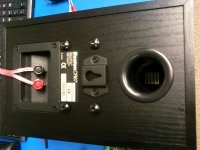
Don't look like yours, no. But maybe do look similar to original A40 series?
4 screws rather than three, and sensitivity the most obvious deviations...
Yet sensitivity does match that Panasonic woofer previously mentioned.
Both seem +4db louder than original system spec. But after Zobels and
padding to match, maybe efficiency boost isn't all that significant...
Just realized dome is not the same size... 3/4 Boston vs. 1/2 TangBand...
Might affect optimum frequency for crossover? Then again, might not...
Still, 5 bucks. Can't sound worse than old dried up one what fell apart.
But what with TB spec? Ferrofluid cooled, yet "NO" ferrofluid enhanced???
Which way is it, folks? Do TB spec writers themselves even know?
Wrap MDF boxes in granite pattern contact paper, for easiest starter.
Not at all durable, but darn easy to replace the finish when it inevitably
gets tore up..
Last edited:
At what power levels does one need to put heatsinks on tweeters? I don't think I'll ever need that.
I should also note that I tore out the original crossovers to make room for the new speakers.
I can save the caps (3.3uF, NP), since they're still sitting around, but the resistors and inductors (iron core) are gone.
- keantoken
I should also note that I tore out the original crossovers to make room for the new speakers.
I can save the caps (3.3uF, NP), since they're still sitting around, but the resistors and inductors (iron core) are gone.
- keantoken
Don't rightly know. Those TB's are only rated 3W RMS, but 80W peak.. Go figure???
I suspect the voice coils are wound light as possible.
More "power handling" might only be dead weight for the same listening sound level.
Heatsink (on the magnet) and ferrofluid, how much extra dissipation does that really
buy you at the coil? Is ferrofluid only useful for damping? What is fluid gap bonus or
penalty to sensitivity in dB per Watt? Don't get me to lying on Ferrofluid.
I can throw you some JBL (probably fake) 2 way crossovers... Arbitrarily Zobel'd
and padded for something else entirely... Or maybe close enough as-is? I havn't
played with em much or re-tuned to any projects of mine, as I've gone 3 way...
Last edited:
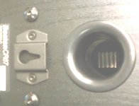
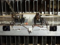
Boston tweeter heatsink I was talking about (barely visible thru port tube) . My camera phone has no flash...
Hello kenpeter
I have work a bit on your photo, here we can see more the tweeter heatsink.
Bye
Gaetan
Attachments

I would be happy to have those crossovers, if you can spare. With the whizzer cones though, should I need a tweeter? I guess I'll just have to find out.
- keantoken
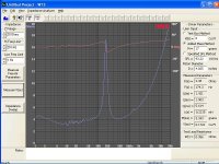
You won't need a tweeter, but you will need a woofer... And I don't merely
mean "sub-woofer". You are gonna have to roll those wizcones in fairly high.
Like maybe 400Hz. There is a terrible Q peak that will rise to above 200Hz
after you stuff it into a box like that...
You might Zobel out electrical component of that peak, but the mechanical
will remain. Only avoid completely by crossing...
Like I said: these are no Fostex... But do sound better than they measure.
WT3 only measures from the terminals, I have no measurement of what it
sounds like in the room.
Attachments
Last edited:
hey guys..love the stuff you write.. and new to this blog thingy...this is for k'token..lol..did you still want the HK avr35 schematics?..i got a drawing of a avr40 board..
I have found a suitable schematic, but thanks for the offer.
Since you're new to the blog thingy... Do you have any projects you've posted online? What is you occupation, etc?
Ken, I finally got that package today. I haven't bothered to count how many trimmer pots you included... And those audio taper Bourns look awesome... And no less than 4 switchers!? The coke can caps sure do look lethal (I feel I should use shorter, larger diameter wires on these since they ARE huge caps, to keep ESR down). Those darlingtons will go to use in the prototypes of my matched +- regulators...
You have an OK to send the 2nd package. I'm twitching to start measuring my 5771/5769 collection with that Hfe function to see exactly how useful my models of those are...
- keantoken
You are gonna need to southern engineer your own HFE rig.
Cheap meter won't test anything but small signal types at
a meaningful current level. Better than no matching at all.
And you probably gonna need primitive bridge to measure L,
C, and ESR. As meters with those features cost hundreds...
The TO3 power transistors are with the second batch, as
none of the big heatsinks would fit the first box.
I have recently discovered that a round TO5 heatsink is
about perfect to clamp pair of smaller TO92 transistors
(D shaped) flat-face to flat-face. And there will be about
a dozen of those in the 2nd batch to assist with thermally
bonding small signal matched pairs as you get them sorted.
And a dozen or more J106 P-JFET singles, have to match pairs yourself...
Then again, they have a funny yellow dot on top. That might mean that
someone else had previously binned them to a tighter spec?
I already sent you plenty of N's and pairs, but no P-JFETs in the first box.
I kept looking for P in matched pairs, but never found any.
Then again, they have a funny yellow dot on top. That might mean that
someone else had previously binned them to a tighter spec?
I already sent you plenty of N's and pairs, but no P-JFETs in the first box.
I kept looking for P in matched pairs, but never found any.
That path leads back to your own PC. We can't see the pictures.
Maybe you can see them fine, and therefore don't realize anything
went wrong...
i figured that much..but was too sleepy to try to attempt any sort of removal..
..anyway...here it is anyway.
Maybe you can see them fine, and therefore don't realize anything
went wrong...
i figured that much..but was too sleepy to try to attempt any sort of removal..
..anyway...here it is anyway.
Attachments
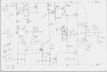
Thanks, Poojita. Strangely, that schematic doesn't look like the same circuit I saw in the manual.
Ken, what's the news on that 2nd package? I think I told you it's okay to send it now.
This is what I've been doing lately...
http://www.diyaudio.com/forums/showthread.php?t=152031
- keantoken
Ken, what's the news on that 2nd package? I think I told you it's okay to send it now.
This is what I've been doing lately...
http://www.diyaudio.com/forums/showthread.php?t=152031
- keantoken
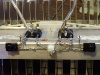
Well, in my free time I've decided to "test my soldering skills" on the Allison.
I think it looks nice! Two pictures are provided since the camera couldn't make up it's mind about flash...
The white thing is a 5771/5769 pair stuck together with heatshrink. The only thing I have yet to add are the bias resistors, which I am at a loss for. I need highish watt 1, 2, and .5 ohm resistors, which I can get locally.
The soldered together leads sticking out from the white thing is the input. The dual resistor is conceptual, theoretically the output will be the middle pin...
- keantoken
Attachments
You have a pair of 2 ohm wirewound slidepots rated 25W each.
These are in little blue Clarostat boxes. Have you opened and
taken a visual inventory yet of whats in side the smaller bags
and boxes?
You have plenty of 0.12ohm wirewound resistors intended to
help bridge the voltage gap between output emitters. Those
were 2 or 3 watts. I wrote it on the bag, but can't recall now.
I gave you enough to fake any reasonable value in series.
Was thinking ahead Allison style when I selected those parts.
More big resistors are coming, but I think I sent you enough
already to more than cover whats requested in post above.
You just might have to get creative with parallel and series...
Last edited:
Whats behind the MJE340? And I'll assume MJE350 though I can't read the number?
I recall the backs of those (collectors?) as bare exposed metal... They can't both
be shorted to the same sink now, or can they???
You are going to have Micas. And wire aplenty, mostly 20ga solid in various colors,
which is also about right gauge for protoboard... I'll send thicker stranded wire too,
but the only color I got extra of is Red, and maybe Black... Hookup type wire with
the tough hard to melt jacket, not "speaker" zipcord style...
Last edited:
Have you checked out Audio Nirvana's "Standard 6.5"?
$95 a pair, not much more than your WallMart specials.
These are much closer to the real Fostex than the junk
you've got now, or the cruddy wizcones I'll be sending.
http://www.commonsenseaudio.com/
$95 a pair, not much more than your WallMart specials.
These are much closer to the real Fostex than the junk
you've got now, or the cruddy wizcones I'll be sending.
http://www.commonsenseaudio.com/
You have a pair of 2 ohm wirewound slidepots rated 25W each.
These are in little blue Clarostat boxes. Have you opened and
taken a visual inventory yet of whats in side the smaller bags
and boxes?
You have plenty of 0.12ohm wirewound resistors intended to
help bridge the voltage gap between output emitters. Those
were 2 or 3 watts. I wrote it on the bag, but can't recall now.
I gave you enough to fake any reasonable value in series.
Was thinking ahead Allison style when I selected those parts.
More big resistors are coming, but I think I sent you enough
already to more than cover whats requested in post above.
You just might have to get creative with parallel and series...
I realized I had those after I turned the computer off. I've already soldered one on (you included 4x2 ohm wirewounds, not 2). Though I worry about balance because my meter doesn't read such low resistances well (either the resistor is way out of tolerance or my meter has problems).
I'm using MJE350/340, ironically, to drive a pair of 1940/5197. This time in Darlington configuration (Last time it was CFP...).
Some time ago, I breadboarded a CFP allison using 2 pairs of 350/340 per rail with .6mA bias current... I hooked it up to my 3" shoebox speaker and by accident, the LTP input stage was horribly off-balance. To this day, that was the most beautiful sound I've ever heard. Crystal clear, not muddy at all, I heard things I never heard before. The harpsichords sparkled and guitar was heavenly against an instrumental background. Those speakers aren't large but they are the best I have. Only one of them still works, something I regret greatly. They came from a broken $30 CD player...
Yes, I've looked at everything in that box, and it all got home safely.
I've seen those 6.5" drivers, but I don't know how long it may be until I have that much money again.
I am going to solder bootstraps next...
- keantoken
Last edited:
- Status
- This old topic is closed. If you want to reopen this topic, contact a moderator using the "Report Post" button.
- Home
- Amplifiers
- Solid State
- Simulation Analysis of several unique Allison-based output stages.