Hi,
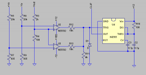
For some time I have been designing an amplifier clipping detector. NE5532 Opamps work as comparators and trigger 555 timer, when output swings close to supply rails. One opamp is for positive, other - for negative rail. Clip on time can be adjusted by resistor R10.
This scheme works in simulations ; do you think it would work in practice? Any ideas how to improve it ? Vout is output of the amplifier.
Regards,
Lukas.
Attachments
I could be wrong, but it seems like the input protection diodes of the NE5532s could mess up the “comparing” function if the values of R7 and R9 are not the same, i.e. to work with non-symmetrical power amplifier clipping behavior (many power amps don’t clip symmetrically). In principle though, it looks like it could work, with maybe another op-amp selection. Also the clip detector’s power should ideally come on before the power amp’s supplies come up, and go down after the power amp’s supplies crash, to prevent a possible latching situation in the op-amps. This in part would depend on the magnitude of the power amp’s rail voltages, and also the final selection of the values of R3,4,5,7,8,& 9. About the only other general comment Id make is to switch to FET input op-amps and raise the input impedance to something more akin to test instrument standards (not 2K). But that’s just me, opinions will vary.
I would have used a comparator as they are designed for this purpose.
In my own amps I use a PIC micro for monitoring outputs and switching off a relay if the output stays at DC. It also provides a 3 second delay before the relay goes on.
I also look at the positive output looking for clipping and light an LED accordingly.
In my own amps I use a PIC micro for monitoring outputs and switching off a relay if the output stays at DC. It also provides a 3 second delay before the relay goes on.
I also look at the positive output looking for clipping and light an LED accordingly.
A better approach might be to compare a buffered version of the input signal to a scaled version of the output signal to look for significant deviations. Comparing the output to the supply rails doesn’t take into account loading factors, e.g. the drop-out point for a 16 ohm load will typically be different than for a 2 ohm load with most amplifiers.
hi
Why do you need the 555 timer?
In Randy Slone's Audiophile's Project Sourcebook one disclosed circuit at fig 8-10 is similar to yours principle but it takes into account loading and power supply sagging too.
Why do you need the 555 timer?
In Randy Slone's Audiophile's Project Sourcebook one disclosed circuit at fig 8-10 is similar to yours principle but it takes into account loading and power supply sagging too.
Thanks for replies. Now I see the problem when supply voltage sags.
I also had an idea to compare input voltage vs output voltage. I'll try to redesign the circuit.
Regards,
Lukas.
I also had an idea to compare input voltage vs output voltage. I'll try to redesign the circuit.
Regards,
Lukas.
somewhere on this board is the schematic for the Apt 1 power amp, which contains a nice clipping indicator. it might be worth searching and taking a look.
good luck!
mlloyd1
good luck!
mlloyd1
Bazukaz said:Thanks for replies. Now I see the problem when supply voltage sags.
I also had an idea to compare input voltage vs output voltage. I'll try to redesign the circuit.
Regards,
Lukas.
Comparing input to output voltage is a reliable method - works regardless of what is causing the clipping - even going into current limit will trigger it. To do this with a classical Lin topology, amplify the difference between the bases of the LTP - and the difference exceeds more than a few millivolts, you've got clip. If the amp is one with an op-amp in the front end - the op amp will reach for the sky the instant the amp loses feedback and you can drive an LED directly.
Sensing overdrive in the VAS (by various means) also works quite well.
- Status
- Not open for further replies.
- Home
- Amplifiers
- Solid State
- Amp clipping detector