...or the death of jfet-matching? 
Jfets are very popular here on DIYAudio and regularly they're matched in the hope to get better performance - some even develop a true art to get closest pairs.
Interestingly there's no data on what this work might bring, in fact it seems a given that the closer automatically the better. No doubt about that, but what to expect? 20% less THD in comparison to unmatched parts? 10%?
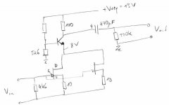
So I scribbled a little circuit together, nothing exciting, see attached, and hooked it up. (Don't be surprised by the odd resistor values, I found them in my parts bin). I used Toshiba 2SK369GR parts as I currently do not have wide spread 2SK170; however 2x 2SK170 equal in parameters a single 2SK369.
You see the THD+N plots in the next post with a big surprise.
A discussion of results and maybe suggestions for additional measurements are highly welcome!
At last, a big thank you to MrG for allowing me the generous use of the AP, a nice little beast.
Have fun, Hannes
Jfets are very popular here on DIYAudio and regularly they're matched in the hope to get better performance - some even develop a true art to get closest pairs.
Interestingly there's no data on what this work might bring, in fact it seems a given that the closer automatically the better. No doubt about that, but what to expect? 20% less THD in comparison to unmatched parts? 10%?
So I scribbled a little circuit together, nothing exciting, see attached, and hooked it up. (Don't be surprised by the odd resistor values, I found them in my parts bin). I used Toshiba 2SK369GR parts as I currently do not have wide spread 2SK170; however 2x 2SK170 equal in parameters a single 2SK369.
You see the THD+N plots in the next post with a big surprise.
A discussion of results and maybe suggestions for additional measurements are highly welcome!
At last, a big thank you to MrG for allowing me the generous use of the AP, a nice little beast.
Have fun, Hannes
Attachments
This is the THD+N for 3 different jfet-pairs and the really interesting point is that matching seems to be completely unimportant THD-wise. It seems that only current has strong influence on THD.
As you can see the jfet-pair A+D, although the worst matched pair, performs best. The only explanation I can find is that its higher current causes a more linear operating point.
Have fun, Hannes
As you can see the jfet-pair A+D, although the worst matched pair, performs best. The only explanation I can find is that its higher current causes a more linear operating point.
Have fun, Hannes
Attachments
the noise is going to be different between the high current and low current devices.
C'mon! Noise differences due to that small gm-variations?
Nevertheless the gentleman is served the noise-less THD-plot.
Please note colours are different.
Have fun, Hannes
Attachments
h_a said:...or the death of jfet-matching?
Jfets are very popular here on DIYAudio and regularly they're matched in the hope to get better performance - some even develop a true art to get closest pairs.
Interestingly there's no data on what this work might bring, in fact it seems a given that the closer automatically the better. No doubt about that, but what to expect? 20% less THD in comparison to unmatched parts? 10%?
So I scribbled a little circuit together, nothing exciting, see attached, and hooked it up. (Don't be surprised by the odd resistor values, I found them in my parts bin). I used Toshiba 2SK369GR parts as I currently do not have wide spread 2SK170; however 2x 2SK170 equal in parameters a single 2SK369.
You see the THD+N plots in the next post with a big surprise.
A discussion of results and maybe suggestions for additional measurements are highly welcome!
At last, a big thank you to MrG for allowing me the generous use of the AP, a nice little beast.
Have fun, Hannes
Pretty much an expected result, I think Scott mentioned this here before, and it also matches my late experience. The whole thing is to match N and P devices (or their parallel incarnations thereof) in complementary designs. This will provide some degree of distortion cancellation.
Regarding noise, I'm not so sure. While in a very simplified model the equivalent noise of paralleled JFETs is scaling down with gm increase and the equivalent source resistance, I'm not so sure this also happens for short channel JFETs like 2SK170 or BF861. My late experiments shows that by paralleling 6x2SK100GR the equivalent noise is actually slightly (5-10%) worse than a single 2SK170V, with the same transconductance. I can think of a few device physics reasons for this behaviour, but it's beyond the scope of this forum.
> It Looks like EUVL's comment is along similar lines.
Exactly.
The circuit used has IMHO no meaning (forgive me for being rude, or honest, depending on how you want to phrase it). It only illustrates the case for paralleling JFETs, where matching is almost a non-issue. Where matching becomes critical is in a distortion cancellation application, of which the LTP is one (of course there are others).
> ...or the death of jfet-matching?
I really couldn't help laughing when I saw this. I'm so sorry !!
Patrick
We discussed that one before :
http://www.diyaudio.com/forums/showthread.php?postid=1691616#post1691616
To do a "Curve Tracer Match", you can drive the gate of the JFET with a functions generator. Say for 2SK170 a triangular wave 10Hz between 0V and -0.5V. Measure current and Vgs with a storage scope and plot in XY mode. Then fit the 1000 datapoint with an nth order polynomial, and you have everything. You can even now use measured data to put into your simulation.
Of course this only works if you apply exact working conditions, like Vds, .......
Patrick
Nice to see my little measurement amuses you guys
Maybe I should not post more in detail investigations then?
While it's nice that some of you guys already knew everything beforehand. I have no doubt that Scott Wurcer or Ovidiu knew that before - they have intimate knowledge AND measurement gear, but as far as I know you two matching champs do not do THD-measurements - so how could you know? Heard somewhere, read in the black book of High-end? I prefer hard data from measurement and here it is.
The circuit above is more or less the frontend used for many, many phonostages and as I'm particularly interested in these I tried that one first. And yes, people also tightly match for this application (in case you missed).
I honestly doubt that the results for LTP are so much different. 'much' in terms of significant THD-reduction. If you believe in distortion spectra reshaping while keeping THD constant, you may feel free to do so. The same for people that think distortion measurements are of no interest; whatever suits you. However you will never know for sure, if nobody does the measurement.
If simple paralleling already shows no effect at all, I would expect only little changes for the LTP - it's the same mechanisms working after all. Honestly I have the impression that if these results are true for Jfets, then they are probably similar for Mosfets - and also there people regularly match tightly.
I mean, come on who would have thought that simply using a slightly higher current part is superior to using matched pairs?
Of course I fully understand that the 2 specialists in tight matching disagree with me - even if they don't have any data to show otherwise
If I'm wrong, I happily withdraw my statements
Have fun, Hannes
PS: just for the log: complementary circuits and offset are a different matter, but that I have not questioned.
And on purpose I did that. Local degeneration is a standard feature for this type of circuit, just have a look at Borbely he even uses much higher degeneration. 10 Ohm is a really low value, as you can easily calculate the gain is nearly not affected at all, so local feedback is pretty minimal.
EDIT:
Sorry I find that completely uninteresting. What interests me is performance in real life circuits not in academic applications. Anyway you can assure yourself by looking at the datasheet that again 10 Ohm has little impact on drain current - you just need a ruler and the datasheet
EDIT2:
You missed the smiley
Maybe I should not post more in detail investigations then?
While it's nice that some of you guys already knew everything beforehand. I have no doubt that Scott Wurcer or Ovidiu knew that before - they have intimate knowledge AND measurement gear, but as far as I know you two matching champs do not do THD-measurements - so how could you know?
Heard somewhere, read in the black book of High-end? I prefer hard data from measurement and here it is.The circuit above is more or less the frontend used for many, many phonostages and as I'm particularly interested in these I tried that one first. And yes, people also tightly match for this application (in case you missed).
I honestly doubt that the results for LTP are so much different. 'much' in terms of significant THD-reduction. If you believe in distortion spectra reshaping while keeping THD constant, you may feel free to do so. The same for people that think distortion measurements are of no interest; whatever suits you. However you will never know for sure, if nobody does the measurement.
If simple paralleling already shows no effect at all, I would expect only little changes for the LTP - it's the same mechanisms working after all. Honestly I have the impression that if these results are true for Jfets, then they are probably similar for Mosfets - and also there people regularly match tightly.
I mean, come on who would have thought that simply using a slightly higher current part is superior to using matched pairs?
Of course I fully understand that the 2 specialists in tight matching disagree with me - even if they don't have any data to show otherwise
If I'm wrong, I happily withdraw my statements
Have fun, Hannes
PS: just for the log: complementary circuits and offset are a different matter, but that I have not questioned.
By using source resistors you are burying some of the difference with the local feedback.
And on purpose I did that. Local degeneration is a standard feature for this type of circuit, just have a look at Borbely he even uses much higher degeneration. 10 Ohm is a really low value, as you can easily calculate the gain is nearly not affected at all, so local feedback is pretty minimal.
EDIT:
What about matching at the operational current? I doubt your circuit passes Idss through the jFET all the time, unless it's a CCS.
Sorry I find that completely uninteresting.
What interests me is performance in real life circuits not in academic applications. Anyway you can assure yourself by looking at the datasheet that again 10 Ohm has little impact on drain current - you just need a ruler and the datasheet EDIT2:
I really couldn't help laughing when I saw this. I'm so sorry !!
You missed the smiley
By the way I just found what Doug Self says on matching parts in a LTP:
Well, if only the relation of Ic vs Vbe (or Id vs Vgs accordingly) is important than that would be another hint that matching won't bring much benefit. But maybe that's a little different for fets.
We'll see
Have fun, Hannes
PS: maybe you get the impression that I'm for whatever reason against matching parts - that could not be more wrong. Don't know about you, but I'm interested nevertheless.
5.1 DISTORTION 1. Input Pair Non-linearity
The input differential pair implements one of the few forms of distortion cancellation that is truly reliable- the transconductance of the input pair are determined by transistor physics rather than matching of variable parameters such as beta. The logarithmic relation between Ic and Vbe is proverbially accurate over eight or nine decades of collector current.
Well, if only the relation of Ic vs Vbe (or Id vs Vgs accordingly) is important than that would be another hint that matching won't bring much benefit. But maybe that's a little different for fets.
We'll see
Have fun, Hannes
PS: maybe you get the impression that I'm for whatever reason against matching parts - that could not be more wrong.
Don't know about you, but I'm interested nevertheless.Ha,
I like your enthusiasm.
I would really like to see information on what effect matching has/hasn't.
But your test set up will not identify the effect of mismatch.
Why is operational current uninteresting?
If I use a Idss = 9mA device and in the circuit it operates in the quiescent state at 6.5mA, then it seems obvious that if I want to examine it's operating characteristics then test/match @ 6.5mA.
If the device sees a range of currents from 5.5 to 7.5mA then test/match over that range.
What is the point of selecting devices that pass 9mA with 0Vgs?
The whole point of the little game was to see real world differences. And real circuits always use degeneration as it is a strong tool to reduce distortion. Examples are Pearl, XOno, Vendetta, Burmester 838 just to name the most popular.
As you see from the thread-title, this was right from the beginning thought to be a series, where one could refine the circuit, also as consequence of discussion.
But if one already sees no benefit at all with the current setup, then such tiny changes as matching at the actual operating point* or keeping case temperature constant are not going to change this. If you assume to have a reasonably linear part at hand, then these are only neglible sideeffects.
Have fun, Hannes
*remember that this is a 2nd order effect; first order I would call the shift of the ID vs VGS curve between parts. If the ID vs VGS curves were perfectly identical between two IDSS-matched parts, then after adding source degeneration there would still be no difference at all (THD-wise, spectra-wise and so on) - the matching would still be perfect.
If however the ID vs VGS curves between the 2 jfets are a little different (tilted), then the matching is no longer perfect. This I would call a 2nd order effect as this should be a neglible effect with decent quality control. At least so far I never heared otherwise.
This would also make matching at more than one working point necessary.
fwiw, in the F5 when I match a K170 with a J74 for close Idss the THD% is lower by several thousandths of a per cent
Sorry, I overlooked your reply previously. Interesting results, although a little depressing. Maybe some data to upload?
Maybe it's more interesting for me to look at real amps instead as this appears at the moment to be a dead end.

Have fun, Hannes
- Status
- This old topic is closed. If you want to reopen this topic, contact a moderator using the "Report Post" button.
- Home
- Amplifiers
- Solid State
- JFet matching and measured distortion - Part1