Hello! I'm subscribing from Tokyo. This is my first post.
I'm inexperienced in amplifier building and repair, but I need to replace a rather unusual electrolytic capacitor in the power supply of a 28W+28W Class A transistor amplifier made by Onkyo in 1976. The component to be replaced is a single large (75 x 110 mm) component but is functionally the equivalent of two 15000uF capacitors connected in series, with the center point connected to the bus earth line. This component has three connectors, "Plus," "E," and "Minus"; it is marked with the values "15000uF + 15000uF 80WV."
Since I have enough room and since I found a cheap source of computergrade capacitors, I am thinking of replacing this component with an array of six identical 12000uF 80V capacitors. (For example, creating two 36,000uF parallel chains and then joining the two chains in series would be one possibility.) Other configurations are also possible, and it would also be possible to use only four of these capacitors rather than six.
Here are my questions:
1) What is the best strategy to take here? Four capacitors? Six? What configuration?
2) Do I need to use balancing resistors? If so, how should I use them?
Thanks for your help!
CDWitmer
P.S. I have scanned photos of the amp, the capacitor in question, and also schematics if anyone feels these are necessary to answer the question. (Obviously I didn't want to post these directly to the board.)
Hiya CD and welcome to the forums...I`m new here too.....back to your question.....you can replace those caps with single ones as you stated with as many as you want in parallel...just make sure they have the same working voltage...and dont use any resistors....just maintain the polarity.
Cheers!! The DIRT®
Cheers!! The DIRT®
If I connect only in parallel, how do I earth?
Joe Dirt, thanks for your reply. Perhaps connecting in parallel w/o resistors is all I need to do; however, I'm curious as to what I need to do about grounding the capacitors . . . the original component has three connectors; the one in the middle is "Earth." If I have all my caps connected in parallel only, where do I put the connection to earth?
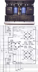
I decided to post a pic of the amp and part of the schematic after all. (I hope this works!) At the bottom of the big caps in the center of the amp, the three connectors can be readily seen. The corresponding parts of the schematic are where the letters are rotated at a 90 degree angle from all the other lettering.
Now, assuming I *shouldn't* connect only in parallel. but need to have a series connection to facilitate earthing as in the schematic, if I have two parallel capacitor "chains" connected in series, can I still get away without resistors? I have read that if only two caps are connected in series, a balancing resistor isn't needed. Can I consider each of the parallel "chains" as a single big cap? Or am I asking for trouble if I hook up capacitors this way without using any balancing resistors?
Thanks very much to all.
Joe Dirt, thanks for your reply. Perhaps connecting in parallel w/o resistors is all I need to do; however, I'm curious as to what I need to do about grounding the capacitors . . . the original component has three connectors; the one in the middle is "Earth." If I have all my caps connected in parallel only, where do I put the connection to earth?
I decided to post a pic of the amp and part of the schematic after all. (I hope this works!) At the bottom of the big caps in the center of the amp, the three connectors can be readily seen. The corresponding parts of the schematic are where the letters are rotated at a 90 degree angle from all the other lettering.
Now, assuming I *shouldn't* connect only in parallel. but need to have a series connection to facilitate earthing as in the schematic, if I have two parallel capacitor "chains" connected in series, can I still get away without resistors? I have read that if only two caps are connected in series, a balancing resistor isn't needed. Can I consider each of the parallel "chains" as a single big cap? Or am I asking for trouble if I hook up capacitors this way without using any balancing resistors?
Thanks very much to all.
Attachments
More of schematic
Hi CD,
would it be possible to post more of this schematic. Need to see where the 'earth' point of your capacitor pair connects to. From what you've already posted it connects to a thicker schematic line and then off the top of the page, though with a line heading back to the ac section of the diagram on the right. Need to determine (at least) if that point is going back to a tap on the transformer.
James
Can I consider each of the parallel "chains" as a single big cap?
If you connect N caps with a capacitiy of X Farads in parallel then you get a thing that behaves as a single big cap with N*X Farads.
Balancing resistors are needed for series connections of caps.
I think your amp has two separate power supplies with center tapped transformers. So you will most probably not need any resistors.
The amp seems to be a nice and tidy construction and worth the hassle of a refit.
Regards
Charles
CDWitmer:
Your amplifier looks very nice. The Class A operation and monaural power supplies suggest that it belonged to Onkyo's premium series. That being the case, I wouldn't be surprised if it includes other technical features that are quite interesting, even by today's standards. It may even be an early MOSFET or vertical power FET design.
What is the model name?
BTW, electrolytics tend to fail over time, and in an elevated thermal environment (such as can be expected in a Class-A power amp), they can leak electrolytic fluid onto the pcb, which will eventually eat away the copper traces and cause a melt-down. A complete replacement of all electrolytics may not be a bad idea if you want your Onkyo to remain operative for many more years. Be especially wary of electrolytic capacitors that have a slight "bulged" surface at the top of the metal cans.
regards, jonathan carr (also in Tokyo)
CD...that is a very nice amp!!!!!....I would almost leave the cover off or replace it with a glass cover.......as far as your question...there are two primary supplies I see....each negative (ground) supply are common to each other...so that being said you could do a bank for each section tieing the the negative to the common ground...your not connecting in series here but in parallel to each rectifier stage...I dont know if I`m explaining this right...if you dont understand I will draw up a quick schematic.
Cheers!!The DIRT®
Cheers!!The DIRT®
Are you sure those caps are bad? Did you try to repower them? What it looks like to me is a +/0/- all in one can. I've never seen that before, although that's not surprising as I've only been about this for 8 or so years. That is a nice looking amp. Love those transformers. Keep at it, as there's enough people here to get it to work.
")
Keep at it, as there's enough people here to get it to work.You guys are great!
Wow, I am really blown away by how kind and helpful you gentlemen are!
I just got back from a concert and despite the fact that the music was absolutely heavenly, I have a splitting headache so I'm not going to answer each of you separately, sorry.
Jonathan, I'm almost certain we've met before. I think we met at a demonstration of a truly awesome analog turntable quite a few years back. If I recall correctly you were living in Suginami Ward and had some sort of a business connected with Scandinavia -- I think the name had "Scan" in it. I was, and still am, living in Tachikawa, albeit with many more kids and much less hair.
Passfan, you would be correct in assuming I don't really know what I'm doing! I'm groping around in the dark. I didn't test these caps; the sound in one channel rapidly degraded -- just a fall-off in volume and general "dirtiness" to the sound -- and all the components in that channel are "tepid" whilst the other (good-sounding) channel gets good and hot. So I said to myself, "After nearly 30 years the capacitors in this amp can't have much life left in them; I'll just replace them all and see if that solves the problem. And if it doesn't I'll send it out to a professional for repairs."
I have a multimeter but using it around such massive caps scares me a bit. Maybe that's just being silly . . .
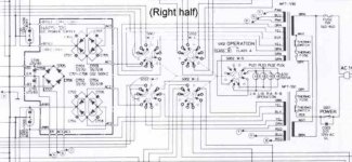
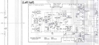
I'm going to post more of the schematic now. The right-hand half goes in this post, and the left-hand half in the next.
Many thanks to you all! Truly a heart-warming group.
Wow, I am really blown away by how kind and helpful you gentlemen are!
I just got back from a concert and despite the fact that the music was absolutely heavenly, I have a splitting headache so I'm not going to answer each of you separately, sorry.
Jonathan, I'm almost certain we've met before. I think we met at a demonstration of a truly awesome analog turntable quite a few years back. If I recall correctly you were living in Suginami Ward and had some sort of a business connected with Scandinavia -- I think the name had "Scan" in it. I was, and still am, living in Tachikawa, albeit with many more kids and much less hair.
Passfan, you would be correct in assuming I don't really know what I'm doing! I'm groping around in the dark. I didn't test these caps; the sound in one channel rapidly degraded -- just a fall-off in volume and general "dirtiness" to the sound -- and all the components in that channel are "tepid" whilst the other (good-sounding) channel gets good and hot. So I said to myself, "After nearly 30 years the capacitors in this amp can't have much life left in them; I'll just replace them all and see if that solves the problem. And if it doesn't I'll send it out to a professional for repairs."
I have a multimeter but using it around such massive caps scares me a bit. Maybe that's just being silly . . .
I'm going to post more of the schematic now. The right-hand half goes in this post, and the left-hand half in the next.
Many thanks to you all! Truly a heart-warming group.
Attachments
Oh yeah, this amp's model is M-955N II / 260
The Onkyo M-955N II / 260 was introduced in 1975.
Yamaha produced something similar, the B-4, in 1978. Probably other Japanese manufacturers had similar offerings, since most of the manufacturers liked to imitate each other.
The thing is just shy of 20 kilos.
It's just a simple, no-nonsense amplifier, at least from the user's perspective.
It didn't cost me very much so I don't have to have a heart attack if I allow the musical smoke to escape from inside the components while trying to repair it -- although I certainly don't want to ruin it since we don't see these old amps as much as we'd like.
God bless and good night!
Rare Classics...
Hi Jonathon,
I have an Onkyo amp from similar era, and similar quality level for it's day.
It is high bias AB design, with two power transformers and four filter caps, and about 100w+100w I expect.
The pre-amp stage has a switched tone control stage (bass and treble selectable turnover frequency switches and boost/cut rotary switches) using caps like 10uF solid caps (size of a matchbox).
The front panel is full of features like pre-amp -20dB mute, power-amp in 0/-10/-20 dB attenuation, Dc/0.1/20 Hz coupling, High cut, Low cut, 2 loudness contours, Stereo/Reverse/L+R mono/L mono/R mono, switchable phono cart loading etc.
Despite all this signal switching and routing, this amp is one of my favorites for all round pleasantness and musicality, and trounces many other amps regardless of age.
Yes, Onkyo did make good and solid (heavy) gear back then, and I would say that these sorts of amplifiers are well worth collecting and renovating.
Eric.
jcarr said:CDWitmer:
Your amplifier looks very nice. The Class A operation and monaural power supplies suggest that it belonged to Onkyo's premium series. That being the case, I wouldn't be surprised if it includes other technical features that are quite interesting, even by today's standards. It may even be an early MOSFET or vertical power FET design.
Hi Jonathon,
I have an Onkyo amp from similar era, and similar quality level for it's day.
It is high bias AB design, with two power transformers and four filter caps, and about 100w+100w I expect.
The pre-amp stage has a switched tone control stage (bass and treble selectable turnover frequency switches and boost/cut rotary switches) using caps like 10uF solid caps (size of a matchbox).
The front panel is full of features like pre-amp -20dB mute, power-amp in 0/-10/-20 dB attenuation, Dc/0.1/20 Hz coupling, High cut, Low cut, 2 loudness contours, Stereo/Reverse/L+R mono/L mono/R mono, switchable phono cart loading etc.
Despite all this signal switching and routing, this amp is one of my favorites for all round pleasantness and musicality, and trounces many other amps regardless of age.
Yes, Onkyo did make good and solid (heavy) gear back then, and I would say that these sorts of amplifiers are well worth collecting and renovating.
Eric.
Re: Here's the left half of the schematic
Can we have a look at the rest of the circuit?
Have you tried doing B & W scans instead of gray scale? Files may be smaller in that way.
Lately I have looking at some Harman Kardon circuits, available from HK's site, particularly models HK770 and HK775, which are power amps that I listened to and liked. The circuits are quite interesting, as they are pure DC with no servo or feedback blocking capacitor. It deserves a look if you have some time.
Carlos
cdwitmer said:Here's the left half of the schematic.
Can we have a look at the rest of the circuit?
Have you tried doing B & W scans instead of gray scale? Files may be smaller in that way.
Lately I have looking at some Harman Kardon circuits, available from HK's site, particularly models HK770 and HK775, which are power amps that I listened to and liked. The circuits are quite interesting, as they are pure DC with no servo or feedback blocking capacitor. It deserves a look if you have some time.
Carlos
Hi-res scan of complete schematic
Clicking on the following links should take you to two scans of the complete schematic. They are black and white, 300dpi, in GIF format.
These are posted at a Japanese website, and your browser will probably "complain" or ask you if you want to download a plug-in to be able to read Japanese on your computer. If you just answer "No" to that error message, the image should display just fine. The image will be displayed in a frame, but if you right-click on the image, you can open it in a new window of its own or download it to your computer for printing.
Each half of the schematic fills an A4 or letter-size sheet of paper if printed at 300dpi.
Also, the free site where these are posted gets busy at certain times of the day, so if you have trouble accessing, it probably means it's a peak traffic period for that site.
If there are any problems, please let me know.
Here's the left side of the schematic
Here's the right side of the schematic
CDWitmer:
Entirely possible that we have met before. I have since moved to Setagaya, right outside of Shimokitazawa, but everything else is as you remembered.
Incidentally, another type of part that commonly fails over time is a switch. And I believe that your Onkyo has speaker output on/off switches, as well as switches for Class A and Class B operation. It is possible that one of these has started to go. Ditto for volume pots.
best, jonathan carr
cdwitmer said:This component has three connectors, "Plus," "E," and "Minus"; it is marked with the values "15000uF + 15000uF 80WV."
Since I have enough room and since I found a cheap source of computergrade capacitors, I am thinking of replacing this component with an array of six identical 12000uF 80V capacitors. (For example, creating two 36,000uF parallel chains and then joining the two chains in series would be one possibility.) Other configurations are also possible, and it would also be possible to use only four of these capacitors rather than six.
Here are my questions:
1) What is the best strategy to take here? Four capacitors? Six? What configuration?
2) Do I need to use balancing resistors? If so, how should I use them?
Thanks for posting the schematic. The centre terminal of the capacitor goes back to a tap on the transformer and so this is a conventional full wave bridge. Balancing resistors are not required in this arrangement.
As for the number of capacitors I would be tempted to replace each capacitor initially with four of your new ones. This gives a capacitance of 24000 uF per half of the old 15000 uF cap which is closer to the original value as designed. The only reason not to use six for each cap is that the charging current through the diode bridge will increase as you add capacitance. Most bridges will cope with the extra current pulses ( which are quite short - a low duty cycle ) so you may be okay with the extra caps.
Hope this is understandable - I can draw you out the capacitor arrangement if required. Joe Dirt has also offered earlier in the thread, I think.
James
Thanks again, Jonathan & James
Yes, Jonathan, I shall check out those other parts that you mentioned. Thanks for mentioning that.
James, I appreciate your confirmation on the earth connection and lack of need for balancing resistors, as well as the suggestion that I try four caps first rather than six. I had been thinking the same thing; even with four I'll end up with something much beefier than before, and I'll not stress the other components so much.
I find it interesting that, providentially, there happens to be another inquiry, posted at almost the same time as mine, that directly applies to mine.
It's thylantyr's "Capacitor Question - Amplifier/Power Supply."
I guess "it never rains but it pours."
You've all be a great source of help and encouragement. I'll report on the outcome!
- Status
- This old topic is closed. If you want to reopen this topic, contact a moderator using the "Report Post" button.
- Home
- Amplifiers
- Solid State
- Need advice on replacing caps in amp P/S