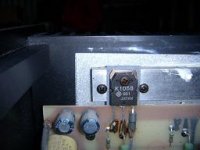
I have bought a secondhand Musical Fidelity P270-2 power amp recently. The amp works fine but someone seems to have replaced the output devices to K1058 and J162 types. The repair seems kind of amateurish so i would be very happy if someone could confirm that these are the correct output devices (or equivalents).
Thanks,
Kenneth
Thanks,
Kenneth
The original amps used the 2SK135/2SJ50 pairs from Hitachi. At least that's what the schematics indicate.
MF had the annoying habit of soldering a wire directly to the MOSFET case, rather than using a proper terminal under one of the screws, so if that's what's under the hood of yours, whoever repaired it has only done what MF themselves did!!
MF had the annoying habit of soldering a wire directly to the MOSFET case, rather than using a proper terminal under one of the screws, so if that's what's under the hood of yours, whoever repaired it has only done what MF themselves did!!
hmm.. bit odd that they have swapped TO-3 cased mosfets for flatpack ones! Unless of course, MF updated the design.
The ferrite should be on the gate lead (pin 1) to help prevent oscillation. If it is on pin 3, it's in the wrong place.
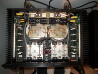
Does it look like there are supposed to be TO-3 cased devices in there? It'll be quite obvious from the drill holes on the heatsink. If it's supposed to be TO-3 devices I would consider putting them back as TO-3's have better thermal dissipation than the flatpacks.
The ferrite should be on the gate lead (pin 1) to help prevent oscillation. If it is on pin 3, it's in the wrong place.
Does it look like there are supposed to be TO-3 cased devices in there? It'll be quite obvious from the drill holes on the heatsink. If it's supposed to be TO-3 devices I would consider putting them back as TO-3's have better thermal dissipation than the flatpacks.
Hi
As Jacco states the original P270's Original P270, "3 pairs of J82/K226 per side".
The original P270 ran very hot and the output devices burned out on some amps and were replaced. The Mk 2 version of the P270 had a lower bias and ran cooler.
I am guessing that you have an early amp with replaced output devices. I have P270 with original devices and one with replaced output devices. They sound the same although the original parts could accept slightly more current.
The beads on one leg of the output device were meant to stop oscillation. I have no idea whether they were really necessary or not - but they were on the original factory supplied amps.
Don
Hi,
After long consideration I decided to join the forum - not any real experience with DIY.
Seen that others had been lucky with getting the schematics to the P270 Mk I in the other related threads, but that is a couple of years ago! Does anyone have the schematics and are willing to share?
I have had my three P270 Mk I for about 9 years with out any problems. Now there seems to be a greater noise when not playing (louder when increased volume). Perhaps a good idea to change the capacitors and do some "spring" cleaning. Perhaps one of you know about increasing noise level - any solution?
Thanks, much appreciated
Licence
I used to work for MF and can confirm that they never had TO3 devices fitted but had 3 pairs of J82/K226 per side. From memory I believe the A470 did use the TO3 devices, 11 pairs per side. Again, from memory, I believe that late model 270-2 amps were fitted with the 2sk1058/j162 as standard from the factory. I don't think your amp has been modded. BTW the ferrite beads on this whole series of amps were NOT fitted to the gates of the mosfets as you would expect.
I have bought a secondhand Musical Fidelity P270-2 power amp recently. The amp works fine but someone seems to have replaced the output devices to K1058 and J162 types. The repair seems kind of amateurish so i would be very happy if someone could confirm that these are the correct output devices (or equivalents).
Thanks,
Kenneth
Hello!
Recently I win this bid for "Musical Fidelity P270-2 Reference" power amp:
Google Dịch
You can see in theres picture the original K1058 and J162 of Hitachi:


Hi again,
Are there any body who have an idea how to decrease the noise floor of the P270 MkI? Which parts to service, substitute etc.?
Thanks!
Licence,
In terms of maximum return for minimum cost/effort, I've had good results doing the following:
- Replacing the input wiring. MF went along with the eighties fad of using solid core wiring (often for outputs as well as inputs). You might want to experiment with 0.4mm diameter silver-plated copper in PTFE (good) or 0.6mm solid core silver in PTFE (better)
- Replacing the 1uf input capacitor for a film and foil type.
- Replacing the LM318 IC for the higher spec LT318 or (if you can get it) LT118. This will reduce the noise floor.
- Replace all PCB electrolytic with 105 degree types. Panasonic FC fit the bill and are good sounding.
Those are the quick and easy things - If you only do one of them - make sure it's the electrolytic capacitor replacement...
Have fun!
")
The Mk1 dropped the rail voltage for the input IC using (woefully under-rated) power resistors. 1k5 and 1k8 from memory (they're easy to spot - they're the ones that have scorched your PCB...) Anyhow, replace them with higher rated types - I managed to squeeze in heatsink-mounted TO-220 packaged resistors.
That mod (along with the electrolytic replacement) should go some way to you avoiding the most common reasons for failure.
That mod (along with the electrolytic replacement) should go some way to you avoiding the most common reasons for failure.
- Status
- This old topic is closed. If you want to reopen this topic, contact a moderator using the "Report Post" button.
- Home
- Amplifiers
- Solid State
- Musical Fidelity P270-2 output devices?