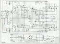
What is wrong with this schematic, I found from some"Pakel ProAudioKit electronic"
I have made this amplifier and with the original Tl 071 I have oscillating problems which depends on position of trim. pot. for bias adjusting, but oscillation and distorsion are also present at any position.
With 741 this amp. working without oscillating ear test, without measurements.
I can post the original PCB of this amp. if it's needed.
Any suggestions are welcome.
Here is my case :
jaycee said:Put 100nF decoupling capacitors to ground on the opamps supply pins, as close to the op. amp as you can.
Thank you for this advice, I will try that, and back here with the result, I really wish to see this amp. working with TL 071 cos 741 is to poor for the highs.
PS: Just my thought: Could the heat sinks on BF 469/470 I putted is big and perhaps too close to the Power transistors MJ 15003/15004?
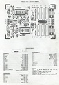
Here is the printed circuit board

I tried with 0.1 mfd caps connected from pin 4 and pin 7 of TL071 to ground , but this has no effect.
When the trim .pot is at min. bias , min. current of the power tr. then the oscillations are the strongest, when is close at the max. position osc. are quite gone , but than the bias is too high and heat of the power tr. are too high, but still I feel , hear that something is wrong with this schematic, according to the sound, very un sure and un stable.
When the trim .pot is at min. bias , min. current of the power tr. then the oscillations are the strongest, when is close at the max. position osc. are quite gone , but than the bias is too high and heat of the power tr. are too high, but still I feel , hear that something is wrong with this schematic, according to the sound, very un sure and un stable.
The leads to the outputs and drivers look like they may be a problem. I would add a 47R base resistor to each of the drivers and a 4R7 to the base of each output device.
I would add a 100R on the output of the opamp where it connects to the node of R6 and R7. I would add about 10pF from Pin 2 to pin 6 of the opamp.
I would add a 100R on the output of the opamp where it connects to the node of R6 and R7. I would add about 10pF from Pin 2 to pin 6 of the opamp.
Really, we need the parts list as well, what other transistors are used etc. We need the whole picture. djk's advice is good though.
Mooly - not neccesarily. Look at ACD's "Lynx" power amp - http://www.audio-circuit.dk/lynx/LYNX-v3-0-schem.pdf
Mooly - not neccesarily. Look at ACD's "Lynx" power amp - http://www.audio-circuit.dk/lynx/LYNX-v3-0-schem.pdf
")
"Pins 2 and 3"
No, I was looking at the RCA handbook for their 100W and 300W amplifier using this same basic circuit, and they use a small cap (7pF~12pF) from pin 2 to pin 6, and the resistor on the output of the opamp (an FET type).
"Really, we need the parts list as well"
http://www.servimg.com/image_preview.php?i=61&u=12272940
I have to agree Mooly.
Bad circuit design!
I'd try decreasing C5 and C8, and remove C10.
MJ15003/4 as drivers?! OMG
I'd throw out this crazy schematic, and would build a working circuit. There are many schematics out there on Diyaudio for +/-70V rails.
PS.: PL300 schema: http://www.audio-circuit.dk/images/schematics/Phase-Linear-300-pwr-sch.pdf
To DJK, AND mOOLY & ALL OTHER INTERESTED PEOPLE!
I just wake up from the horror dream, but when I see that so many help on the forum now I am happy and not alone!
THANK YOU ALL FOR THE HELP, AND i AM READY TO DO ANYTHING TO HEAR A GOOD SOUND FROM THIS PIECE OF BOX.
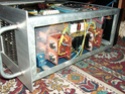
i SPENT 3 OR 4 MONTHS TO GET ALL PARTS : 2 KW TOROID TRANSFORMER(WOUND BY MY HANDS, BIG ALU HEATSINKS TAKEN FROM SIEMENS INDYSTRY (MOTOR CONTROL CIRCUIT) AND ALL OTHER THINGS LIKE BOX AND FRONT ALU. PANEL IS MADE BY MY HANDS BUT THIS WORKS ONLY WITH 741 WHICH I PUTED IN THE SOCKET COS TL071 AND ALSO TRIED NE 5534 NOT WORK PROPERLY!!!
THE PARTS LIST I ALREADY POSTED IN THE JPG. FORMAT.
T5: YES I PUTTED ON THE MAIN HEATSINK AND CONNECT WITH 3 TWISTED WIRES LENGT ABOUT 15 CM.
ALSO I TRIED AND CONNECTED A 18 PF CAPACITOR FROM PIN 2 TO PIN 6 DIRECT SOLDERED ON THE OP.AMP, AND NOTHING DONE, STILL THE SAME BAD OSCILLATIONS!
PLEASE WHAT TO DO NOW???
i CAN POST THE CLOSE UP IMAGES OF WHOLE AMP IN MY CASE.
THE MAN WHO GAVE ME THIS SCHEMATIC TOLDS ME THAT THIS AMP. WAS WORKING WHEN HE MADE IT LONG TIME AGO!OR ...OR WHAT IS THE BEST FOR ME? TO BUILD A COMPLETELY NEW MODULES BUT TO KEEP UP EVERYTHING LIKE POWER TRANSISTORS MJ 15003/15004???
PLEASE HELP, CAN i MAKE THIS WORK OR TO START MAKING OTHER WORKING MODULES BUT I WANT TO HAVE SAME POWER: THIS SCHEMATIC IS RATED 450W @ 4OHM, 280W @ 8 OHM
THD (1KHZ)=0.01
FREQ. RESP.=10 HZ-80 KHZ
SNR=100dB
I just wake up from the horror dream, but when I see that so many help on the forum now I am happy and not alone!
THANK YOU ALL FOR THE HELP, AND i AM READY TO DO ANYTHING TO HEAR A GOOD SOUND FROM THIS PIECE OF BOX.
i SPENT 3 OR 4 MONTHS TO GET ALL PARTS : 2 KW TOROID TRANSFORMER(WOUND BY MY HANDS, BIG ALU HEATSINKS TAKEN FROM SIEMENS INDYSTRY (MOTOR CONTROL CIRCUIT) AND ALL OTHER THINGS LIKE BOX AND FRONT ALU. PANEL IS MADE BY MY HANDS BUT THIS WORKS ONLY WITH 741 WHICH I PUTED IN THE SOCKET COS TL071 AND ALSO TRIED NE 5534 NOT WORK PROPERLY!!!
THE PARTS LIST I ALREADY POSTED IN THE JPG. FORMAT.
T5: YES I PUTTED ON THE MAIN HEATSINK AND CONNECT WITH 3 TWISTED WIRES LENGT ABOUT 15 CM.
ALSO I TRIED AND CONNECTED A 18 PF CAPACITOR FROM PIN 2 TO PIN 6 DIRECT SOLDERED ON THE OP.AMP, AND NOTHING DONE, STILL THE SAME BAD OSCILLATIONS!
PLEASE WHAT TO DO NOW???
i CAN POST THE CLOSE UP IMAGES OF WHOLE AMP IN MY CASE.
THE MAN WHO GAVE ME THIS SCHEMATIC TOLDS ME THAT THIS AMP. WAS WORKING WHEN HE MADE IT LONG TIME AGO!OR ...OR WHAT IS THE BEST FOR ME? TO BUILD A COMPLETELY NEW MODULES BUT TO KEEP UP EVERYTHING LIKE POWER TRANSISTORS MJ 15003/15004???
PLEASE HELP, CAN i MAKE THIS WORK OR TO START MAKING OTHER WORKING MODULES BUT I WANT TO HAVE SAME POWER: THIS SCHEMATIC IS RATED 450W @ 4OHM, 280W @ 8 OHM
THD (1KHZ)=0.01
FREQ. RESP.=10 HZ-80 KHZ
SNR=100dB
djk said:"Pins 2 and 3"
No, I was looking at the RCA handbook for their 100W and 300W amplifier using this same basic circuit, and they use a small cap (7pF~12pF) from pin 2 to pin 6, and the resistor on the output of the opamp (an FET type).
"Really, we need the parts list as well"
http://www.servimg.com/image_preview.php?i=61&u=12272940
I have posted parts list, that is what i have here, if you don't understand , please ask me, but i hope you won't.
To ANDREW: WHERE CAN I FOUND VOLTAGE AMPLIFIER PROJECT AND HOW TO MATCH TO THE REST OF THIS AMP?
What's the value of C10?
Try changing it. Both a too small value and a too big one will cause oscillation.
The amplifier is not stable without it so don't remove it like someone said.
Unlike the commonly used topology the op-amp provides 90 degrees of phase shift and the VAS another 90 degrees at high frequencies so the capacitor providing lead is absolutely neccessary for stability unlike in normal amps.
megajocke said:What's the value of C10?
Try changing it. Both a too small value and a too big one will cause oscillation.
The amplifier is not stable without it so don't remove it like someone said.
Unlike the commonly used topology the op-amp provides 90 degrees of phase shift and the VAS another 90 degrees at high frequencies so the capacitor providing lead is absolutely neccessary for stability unlike in normal amps.
Thank You Megajocke!
The value of the c10=68pf/ceramic
All values can be seen here:
http://www.servimg.com/image_preview.php?i=61&u=12272940
What value do you recommend me from min to max?
megajocke said:What's the value of C10?
Try changing it. Both a too small value and a too big one will cause oscillation.
The amplifier is not stable without it so don't remove it like someone said.
Unlike the commonly used topology the op-amp provides 90 degrees of phase shift and the VAS another 90 degrees at high frequencies so the capacitor providing lead is absolutely neccessary for stability unlike in normal amps.
That cap is the key to getting this stable. I've made many many many of these to work - including kilowatters. In addition to the 90 degrees thru the opamp and the 90 thru the VAS, you get a few extra degrees through the outputs. Normally you can ignore them, but not here. Tap the lead compensation cap from the output of the VAS, NOT the output of the amp. And the value will need to be determined experimentally, unless you do a Bode analysis of the circuit (in which case you can nail it the first time).
- Status
- This old topic is closed. If you want to reopen this topic, contact a moderator using the "Report Post" button.
- Home
- Amplifiers
- Solid State
- 741 op.amp works, tl 071 is oscillating?