Qurtre Amplifier ???
As I was going through all my hidey holes of old Electronics I found a very heavy Qurtre Amplifier. I hooked it up and all seems well and works good and sounds good....But, I know nothing about this Amp as there is no name plate or other ID anywhere except the Qurtre Name on the Silver brushed front panel with one tiny red power light on the front bottom center. Any input as to what I have here is appreciated. Searched the web with basically no information.
Thanks
Bill
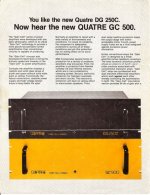
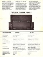
If those are Quatre's, I have two of those or at least most of the pieces. Way back when (maybe like late 70's??), the Quatre DG-250c and a pair of Dahlquist DQ-10's was considered a fine combination. If nothing else, you have a hefty power transformer and chassis to use for other projects.
The transistors used for the VAS and pre-drivers in those amps was prone to blowing out. It can be replaced easily. There is also room on those heatsinks to drill out for 3rd pair of output transistors so that it can more reliably drive a 4 ohm load, and it is a fairly simple task to convert the quasi-complementary o/p stage to full complementary.
If those are Quatre's and you decide to get rid them, I would be interested in them. I have a very fond spot in my heart for those amps.
Phil
ThanksPH104 said:If those are Quatre's, I have two of those or at least most of the pieces. Way back when (maybe like late 70's??), the Quatre DG-250c and a pair of Dahlquist DQ-10's was considered a fine combination. If nothing else, you have a hefty power transformer and chassis to use for other projects.
The transistors used for the VAS and pre-drivers in those amps was prone to blowing out. It can be replaced easily. There is also room on those heatsinks to drill out for 3rd pair of output transistors so that it can more reliably drive a 4 ohm load, and it is a fairly simple task to convert the quasi-complementary o/p stage to full complementary.
If those are Quatre's and you decide to get rid them, I would be interested in them. I have a very fond spot in my heart for those amps.
Phil
The logo is script and looked like QURTRE but can also be read as QUATRE which is probably the correct spelling as you said. My plan was to use this amp or my Dynaco 120 for powering my Dahlquist DQ-10s for easy listening. I presume by the number that this amp is 250W. Is this correct? If I do not use them I would entertain the idea of letting them go. I do not know the value as I cannot find information on them. Thanks for the mod ideas.
jacco vermeulen said:I though David Gore designed a bunch of gain cell models ?
That amp was called a gain cell amp. As I recall, that amp also had a rather high failure rate, possibly approaching 100%.
They did Steve. The pair I inherited were used to drive an old pair of Infinity 4.5's. It was the VAS and pre-drivers that went out. I replaced those in my old ones and added the third pair of o/p transistors and never had a bit of problems with them, and some magical sounds if my memory is right. I would sure like to compare those to a modern amp - to the point of building a modern version of them. And they were actually more reliable once the protection circuits were removed.
And I'm having trouble posting the ad sheet,,,,,,,,,, stay tuned.
Phil
And I'm having trouble posting the ad sheet,,,,,,,,,, stay tuned.
Phil
Steve
Quatre did something on that amp that I don't understand. Maybe you can help....
The input is a simple differential npn pair biased with a npn current source referenced to the negative voltage rail. The ref voltage to the base of the current source transistor was a zener bypassed with a largish cap - few hundred uF if my memory is right. The emitter was connected to the neg rail through a resistor to define the current - so far, so good. But that resistor (it was a few k - maybe like 4 - 5K) was also in parallel with a series r-c from the emitter to the neg rail -- about 100 uF and the resistor was the same value as the single resistor used to set the current. I hope I'm I'm clear here.
Any thoughts on the purpose of the extra R and C?
thanks
Phil
PH104 said:Steve
Quatre did something on that amp that I don't understand. Maybe you can help....
The input is a simple differential npn pair biased with a npn current source referenced to the negative voltage rail. The ref voltage to the base of the current source transistor was a zener bypassed with a largish cap - few hundred uF if my memory is right. The emitter was connected to the neg rail through a resistor to define the current - so far, so good. But that resistor (it was a few k - maybe like 4 - 5K) was also in parallel with a series r-c from the emitter to the neg rail -- about 100 uF and the resistor was the same value as the single resistor used to set the current. I hope I'm I'm clear here.
Any thoughts on the purpose of the extra R and C?
thanks
Phil
Without seeing a schematic I can't say for sure. It sounds like they set a current for the DC and set another current for the AC. At frequencies the cap would pass the resistors were parallel and twice the current would flow.
I don't believe it would work that way. Maybe they did. There might be a clue in the patent. I will read it.
thanks Steve. It's nothing I've ever seen before and couldn't figure why they did it either.
The cap starts to pass AC at about 5 KHz. I used to have a schematic but think it got lost in moves and house cleanings over the past 25 years. But this is one thing that always stuck in my mind.
The cap starts to pass AC at about 5 KHz. I used to have a schematic but think it got lost in moves and house cleanings over the past 25 years. But this is one thing that always stuck in my mind.
The transistors used for the VAS and pre-drivers in those amps was prone to blowing out. It can be replaced easily. There is also room on those heatsinks to drill out for 3rd pair of output transistors so that it can more reliably drive a 4 ohm load, and it is a fairly simple task to convert the quasi-complementary o/p stage to full complementary.
Thanks for the info--
I tried to post an image of my Quatre but it was too big and have no way to make it smaller yet. I will try again later.
When you say "simple task" to do these conversions I presume that you mean that would be with some instructions
 I used to be proficient in electronics about 45 years ago but have lost so much of my electronics design abilities but can still follow instructions and build OK.
 I am trying to get back to my old roots of listening to the Rock & Roll that I remember from the 60s & 70s but my new sound system upgrades over the years just does not cut it. I now view them as downgrades. I went to Craigs List a couple weeks ago and found an old rock band musician getting rid of his GOOD stuff. 15" JBLs with EV Horns in ugly black cabs and hooked them up to a couple Phase Linear 400s I just purchased. Now I am a happy camper and can enjoy the rock concert sounds like I remember.
PH104 said:The input is a simple differential npn pair biased with a npn current source referenced to the negative voltage rail. The ref voltage to the base of the current source transistor was a zener bypassed with a largish cap - few hundred uF if my memory is right. The emitter was connected to the neg rail through a resistor to define the current - so far, so good. But that resistor (it was a few k - maybe like 4 - 5K) was also in parallel with a series r-c from the emitter to the neg rail -- about 100 uF and the resistor was the same value as the single resistor used to set the current. I hope I'm I'm clear here.
Any thoughts on the purpose of the extra R and C?
Turn on thump suppression.
Bill --
I'd be happy to provide some instructions if I can find my notes -- I know what to do, just not sure of the part numbers, etc., to be able to tell you how. I'll look around. But to get started, there are 4 transistors on each board, each is a little block-looking thing (would have to look up case style) with a part number starting in MPS or maybe MDS or even 2N. They are likely true Motorola parts. They have a thin copper or bronze heatsink tab sticking out the top. Those are the ones that will blow out. Find those and I can give you some hints. On the other hand, the amp should be perfectly happy with your DQ-10s and you can likely get away with doing nothing. If I remember right, the DQ-10s impedance doesn't drop much below 6 ohms.
Are there TO-3 output transistors (4 per heat sink) that are RCA parts with some weird number? If so, they are all NPN devices and can be replaced with MJ15003s or MJ15024s. I know there are more modern parts but I also know these work reliably in that circuit. These transistor swaps won't give you big sonic gains, just enhance reliability.
Or - I would be happy to do some upgrades for you at little/no cost unless I run into something unexpected which is unlikely since your amp works. Why you ask? I would love to hear that amp again. You can email me through diyaudio if you're interested or have specific circuit questions.
Happy listening!
Phil
- Home
- Amplifiers
- Solid State
- Quartre Amplifier ???