Hi everybody!
I designed a non original, very simple buffer/polarity switch, originally meant to be used as a first stage in a headphone amplifier. I’m not a EE, nor I have a formal (nor informal) background in electronics and this is my first transistor circuit, so I’m very embarassed to post something in the temple of solid state. So, please, be indulgent towards my mistakes.")
The ideas (changed a bit over time) were:

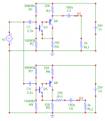
Please note that the duplicated components in the picture are just for simulation purposes. If there’s something good in the circuit, I must say thanks to PRR; for the idea of using a Sziklai, thanks to Chu Moy and Millwood, all at headwize.com.
The simulated distortion is not bad, with 2nd, 3rd and 4th harmonics quickly decreasing. I’m aware that simulated figures are not very reliable (especially when they contain many zeroes) but, at least, this encourages me to build the circuit.
At 0.4 Vpeak output:
Inverting: 0.007 2nd 0.00016 3rd 0.00001 4th
Non-inverting: 0.009 2nd 0.0002 3rd 0.00001 4th
At 2V Vpeak output:
Inverting: 0.037 2nd 0.005 3rd 0.0006 4th
Non-inverting: 0.050 2nd 0.007 3rd 0.001 4th
In the simulation, the inverting output show signs of bad mannered distorsion after 5 Vpeak (3.5 Vrms), the non inverting after 4.3 Vpeak (3 Vrms).
Now, some (I’m afraid eventually stupid) questions.
I designed a non original, very simple buffer/polarity switch, originally meant to be used as a first stage in a headphone amplifier. I’m not a EE, nor I have a formal (nor informal) background in electronics and this is my first transistor circuit, so I’m very embarassed to post something in the temple of solid state. So, please, be indulgent towards my mistakes.
The ideas (changed a bit over time) were:
- high input impedance, around 100k;
- low output impedance, around 200 Ohm (330 in the final version); load 2k Ohm or more;
- same gain, input and output impedance for both inverting and non inverting output
- at least 2Vrms of voltage swing.
Please note that the duplicated components in the picture are just for simulation purposes. If there’s something good in the circuit, I must say thanks to PRR; for the idea of using a Sziklai, thanks to Chu Moy and Millwood, all at headwize.com.
The simulated distortion is not bad, with 2nd, 3rd and 4th harmonics quickly decreasing. I’m aware that simulated figures are not very reliable (especially when they contain many zeroes) but, at least, this encourages me to build the circuit.
At 0.4 Vpeak output:
Inverting: 0.007 2nd 0.00016 3rd 0.00001 4th
Non-inverting: 0.009 2nd 0.0002 3rd 0.00001 4th
At 2V Vpeak output:
Inverting: 0.037 2nd 0.005 3rd 0.0006 4th
Non-inverting: 0.050 2nd 0.007 3rd 0.001 4th
In the simulation, the inverting output show signs of bad mannered distorsion after 5 Vpeak (3.5 Vrms), the non inverting after 4.3 Vpeak (3 Vrms).
Now, some (I’m afraid eventually stupid) questions.
- The Sziklai has huge current gain. For biasing its base I used much smaller resistor values than those would be needed. The idea was that too a high impedance would make the circuit prone to RF. Is this a good (or bad) idea? Is this enough not to catch RF? (Provided that the supply rail be properly decoupled)
- Is there a risk of oscillation and need of using a “gate stopper” like if the Sziklai were a mosfet?
- Is there something else wrong with the circuit?
- Could it be improved with a current source? (I guess it would destroy its simmetry.)
- Is the voltage swing big enough to use the circuit as a preamp for modern sources?
[/list=1]
Thanks a lot for reading as well as for your answers.
Massimo
P.S. I had so much fun with this circuit, much more than with opamps. Who knows why…
Attachments
Hi CBS240,
thanks for your kind answer!
To be sincere, having looked at the TIP120 datasheet and having read... Wikipedia... I had the impression from the beginning that the resistor you mentioned was needed. But my very poor math skills and the encouraging yet probably inaccurate simulation results made me overlook the problem.
Anyway, would you please allow me some time to see if I can compute by myself the new bias resistors? Then I'd be very grateful if you could check my math... May I ask your help once again?
Thanks anyway
Massimo
thanks for your kind answer!
To be sincere, having looked at the TIP120 datasheet and having read... Wikipedia...
I had the impression from the beginning that the resistor you mentioned was needed. But my very poor math skills and the encouraging yet probably inaccurate simulation results made me overlook the problem.Anyway, would you please allow me some time to see if I can compute by myself the new bias resistors? Then I'd be very grateful if you could check my math... May I ask your help once again?
Thanks anyway
Massimo
Hi Lineup, thanks for your answer.
In fact, my insane desire to build a polarity switch originated from a lovely opamp circuit designed by Steven. Of course, I didn't even conceive the idea of making something better. I just hoped to make... something.
In the meanwhile, I fell in love with the idea of trading current for distortion, optimizing for lower 3rd harmonics, you know what I mean...
Ciao e grazie,
Massimo
No math, only sim
Hi CBS240,
since failing is an art, I decided to take the shortest path to failure, i.e. to simulate without knowing exactly what's behind (yes, I need to do more homework...).
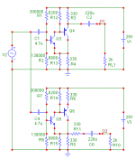
Anyway, the result is the attached circuit, 1.2 mA through Q3/Q5. The simulated distortion shows a marked improvement for the inverting out, less for the non-inverting. The improvement should be more marked near the clipping level. Here are the figures, hopefully not entirely meaningless...
At 0.4 Vpeak output:
Inverting: 0.005 2nd 0.00008 3rd 0.00001 4th
Non-inverting: 0.008 2nd 0.00017 3rd 0.00001 4th
At 2V Vpeak output:
Inverting: 0.025 2nd 0.003 3rd 0.0003 4th
Non-inverting: 0.041 2nd 0.005 3rd 0.0008 4th
I also attempted to increase current to around 2mA through Q3/Q5, without any (simulated) improvement.
Good enough to build?
Ciao,
Massimo
Hi CBS240,
since failing is an art, I decided to take the shortest path to failure, i.e. to simulate without knowing exactly what's behind (yes, I need to do more homework...).
Anyway, the result is the attached circuit, 1.2 mA through Q3/Q5. The simulated distortion shows a marked improvement for the inverting out, less for the non-inverting. The improvement should be more marked near the clipping level. Here are the figures, hopefully not entirely meaningless...
At 0.4 Vpeak output:
Inverting: 0.005 2nd 0.00008 3rd 0.00001 4th
Non-inverting: 0.008 2nd 0.00017 3rd 0.00001 4th
At 2V Vpeak output:
Inverting: 0.025 2nd 0.003 3rd 0.0003 4th
Non-inverting: 0.041 2nd 0.005 3rd 0.0008 4th
I also attempted to increase current to around 2mA through Q3/Q5, without any (simulated) improvement.
Good enough to build?
Ciao,
Massimo
Attachments
Hi
I guess the idea is to switch the load from one side to the other? To me, this circuit is known as a feedback pair. For just 2Vp, why use 25V? If your intent is to bridge two amplifiers, there may be issues. What is the source and the load intended to be? TIP120 is not that great, IMO, unless you’re using them for a switch.
I think op-amps would be a better way to go with this signal level. If you want to make a phase splitter circuit, op-amps can be good there too. If you need a very good phase splitter, there are great IC's that do that task and are simple to implement. I think THAT corp. makes one, I'm sure there are others. I made a discrete phase splitter circuit w/gain that will way out do anything you can make with op-amps, but it's a bit complex. Sort of a ‘discrete op-amp’ project.
I guess the idea is to switch the load from one side to the other? To me, this circuit is known as a feedback pair. For just 2Vp, why use 25V? If your intent is to bridge two amplifiers, there may be issues.
What is the source and the load intended to be? TIP120 is not that great, IMO, unless you’re using them for a switch. I think op-amps would be a better way to go with this signal level. If you want to make a phase splitter circuit, op-amps can be good there too. If you need a very good phase splitter, there are great IC's that do that task and are simple to implement. I think THAT corp. makes one, I'm sure there are others. I made a discrete phase splitter circuit w/gain that will way out do anything you can make with op-amps, but it's a bit complex.
Sort of a ‘discrete op-amp’ project. Apologies
Hi CBS240,
first of all, humblest apologies for misleading you with my unclear schematics and even worse explanations.
Yes, the circuit is a simple phase splitter where the load (the 2k resistor) is connected to the circuit through a switch that takes the signal either from the emitter or from the 330R resistor connected to the collector of the BD140; the 330R resistor is there just to raise the impedance at the same level of the inverting output, so the gain of the two outputs shall be the same for any load.
Why two copies of the circuit in the attached schematics? Just to be able to simulate gain, impedance, etc. together for both the inverting and the non inverting "mode" with the same simulator file.
Other apologies for mentioning TIP 120 and...Wikipedia. The TIP 120 Darlington datasheet shows two resistors connecting base and emitters of the two transistors. Wikipedia recommends to use a similar resistor on the feedback pair too, that (I think) would solve in a slightly different way (introducing some feedback) the "minimum current" problem you mentioned. Anyway, thanks very much for the advice! Do you think I correctly implemented what you proposed? Please note I added also a 6800 ohm resistor in parallel to R4, just to equalize the gain for both outputs.
Source and load. The circuit should be connected as follows:
Source (CD, FM Tuner, tape deck or phono preamp) -> Potentiometer (e.g. 25k) -> THIS CIRCUIT -> phase switch -> output selector switch -> crossfeed followed by headphone driver OR power amplifier and speakers.
I think most modern sources should not output more than 2Vrms (maybe this could not be true for phono preamps), so I "tuned" the circuit to clip just over this level. Am I right?
The crossfeed is a acoustical simulator for headphone listening that mimics the "mixing effect" that happens when we listen at speakers, with the left ear hearing most of the sound of the right speaker and vice-versa. The "mixing effect" is simulated though a R-C network and serves the purpose of avoiding the "super-stereo" effect of headphone listening. This is the circuit:
http://www.meier-audio.homepage.t-online.de/
For optimal frequency response and optimal crossfeed level, the component values must be computed (see formulas in the page linked above) starting from source impedance (the 330 ohm of this circuit) and load impedance (the headphone driver). This is the reason for "equalizing" the impedance of the noninverting output with additional 330ohm resistor. This way, the behaviour of the crossfeed would be independent on the phase of the signal.
The reasons for doing the polarity switch this simplistic way were (1) the curiosity of seeing how far I could go with a single transistor (yes there are two...) using a lot of quiescent current (20mA) and no feedback, (2 - most important) my ignorance about solid state design. When my math shall improve, I'll try something different but, all in all, this is a start...
Ciao and many many thanks!
Massimo
More background about the 2Vrms topics...
Initially, this circuit was powered at 15V, clipped just below 2Vrms and had 3 times distortion. Raising the voltage to 25Vrms, distortion dropped and the voltage swing improved (3Vrms). If this is not needed, Vce of BD140 can be "narrowed" at the benefit of lower distortion.
At least, this is what my simulator says...
Massimo
Hi Lineup,
thanks for your kind words. But since my last post I got the impression that there is more juice to squeeze from this simple circuit. Unfortunately I couldn't work enuogh on it, but soooner or later I'll show a complete and hopefully better performing (or simulating) preamp.
Ciao!
Massimo
P.S. I love Sweden. Why don't you lend us some honest politicians? We could give you in exchange many bottles of good red wine...
thanks for your kind words. But since my last post I got the impression that there is more juice to squeeze from this simple circuit.
Unfortunately I couldn't work enuogh on it, but soooner or later I'll show a complete and hopefully better performing (or simulating) preamp.Ciao!
Massimo
P.S. I love Sweden. Why don't you lend us some honest politicians? We could give you in exchange many bottles of good red wine...
I would not say NO to one bottle of wine.There are good and bad politicians in any country,
may it be sweden, south-africa or USA.
Dont make too much ILLUSIONS about swedish people.
Man is man and woman is woman, for good AND bad
.. like he/she was already 2000 years ago:
- He among you wants to be biggest
.. he be the servant, the waiter, waitress to serve others!
your halo
Hello swedish friend...
I don't want to hijack my own thread, but let me say one anecdote.
In 2008 me and my wife had a 10 days vacation in Sweden. After coming back to the hotel in the evening, we used to watch some tv, just to see if there were differences with the italian tv channels and eventually to discover something more about swedish people.
I think the most impressive differences were the lack of:
1. naked girls in the advertisements, quiz shows and other shows;
2. interviewed politicians in the tv news.
After that I started to think that there must be a relationship between naked girls and politicians, at least in Italy. So, if you want to see the girls, you also get politicians.
So let me dream of your country, at least for a while.
Have a lovely swedish evening!
Massimo
P.S. Apologies to the ladies reading my post. Hope you'll understand what I mean.
- Status
- This old topic is closed. If you want to reopen this topic, contact a moderator using the "Report Post" button.
- Home
- Amplifiers
- Solid State
- The simplest polarity switch