Greetings,
I just got a BGW 620B and it looks like somebody hardwired the thing to be bridged mono. The stereo/mono switch is missing and the left side input is showing up on both ouputs. I want to restore the two channel ability.
Does anybody know if BGW factory configured any of these for mono?
I have the 620 and 750B schematics and the circuit s are virtually identical with the exception of fan-control, etc. for the 750B. The 620 looks to be different than the 620B. (Not sure yet though...)
Before I start doing exploratory surgery, does anybody have a schematic of the 620B that I can reference? Thanks.
JW
I have since fixed the amplifier. It wasn't bridged as I thought earlier.
Somebody physically broke the right channel attenuator from the sub-board and to "fix" the problem routed the output from the left channel to both the left and right output connectors. Whatever...
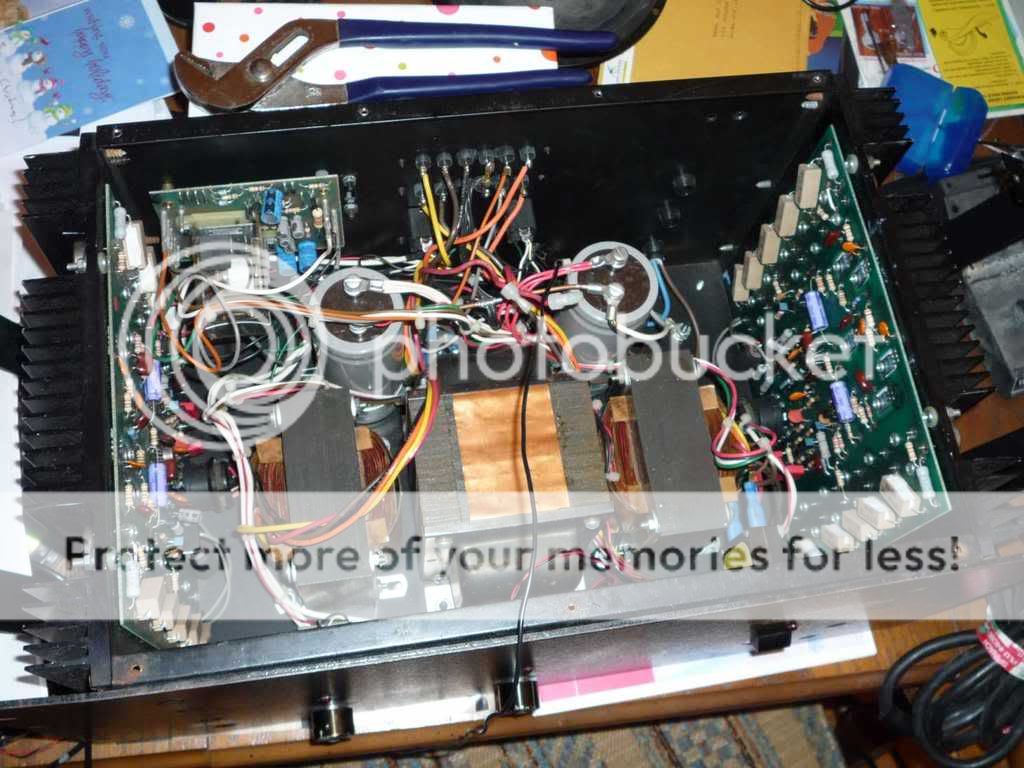
Here are the the pictures of the amplifier for those who might be interested. The two transformers flanking the power transformer are for matching to 70V and 25V if needed.
Somebody physically broke the right channel attenuator from the sub-board and to "fix" the problem routed the output from the left channel to both the left and right output connectors. Whatever...
Here are the the pictures of the amplifier for those who might be interested. The two transformers flanking the power transformer are for matching to 70V and 25V if needed.
Hi walker112,
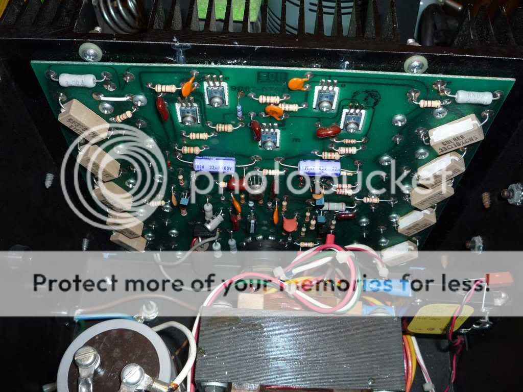
That PCB looks almost identical to the layout of the BGW750C. That is a good thing. I've serviced many of those and they can sound pretty good. Is that metal can op amp an LM318 by chance?
We used to correct the DC balance by adjusting one of the current sources (by padding the current set resistor) while monitoring the output of the LM318. You adjusted the current sources until the output of the LM318 was below | 100 mV | VDC.
If found that this amp responded well to matching the outputs and complimentary transistors.
-Chris
anatech said:Hi walker112,
That PCB looks almost identical to the layout of the BGW750C. That is a good thing. I've serviced many of those and they can sound pretty good. Is that metal can op amp an LM318 by chance?
We used to correct the DC balance by adjusting one of the current sources (by padding the current set resistor) while monitoring the output of the LM318. You adjusted the current sources until the output of the LM318 was below | 100 mV | VDC.
If found that this amp responded well to matching the outputs and complimentary transistors.
-Chris
Chris,
Yes, that's a LM318 in the metal package. From the schematics, this amp appears to be a close relative to the 750's.
I've added some real binding posts to the chassis and some bypass caps. Eventually I plan to beef up the power supply, but it does sound pretty decent as is through my EPI 100 garage speakers.
The amp itself looks like it's five rack spaces high, so there's plenty of room to add and change things. And there's no noisy fan.
Hi walker112,
Increasing the size of the filter caps is a complete waste of money. These were not undersized. Maybe just new ones will have better high frequency characteristics, then add bypass caps. That will help more than increasing the capacitance.
If you have the schematic for the 750C, follow the same procedure to balance the amp so your op amp offset is low. This board doesn't look like it has the extra pads for this. Also, replace the ceramic caps with Polystyrene or Mica. That will improve the top end.
If it's possible, can you scan the schematic, PCB layout and adjustments for me? I haven't got this one. A parts list would be nifty also. If this is a problem, then don't worry about my request.
I wouldn't mind having a look at this newer version. To be honest with you, I really liked the 750C amps and wouldn't mind getting some to update. They were very reliable. I'm wondering if a newer fast BJT type single op amp wouldn't improve the sound quality, but the LM318 will slew at 70 V/uS in feed forward. That's pretty respectable.
-Chris
- Status
- This old topic is closed. If you want to reopen this topic, contact a moderator using the "Report Post" button.
- Home
- Amplifiers
- Solid State
- BGW 620B help/schematic wanted