Schematic can be found here, into Jan Dupont pages:
http://www.audio-circuit.dk/images/schematics/Quad-405-pwr-sch.pdf
I would love to have the detailed circuit description ..including each transistor function, the audio patch map.
Write it here, or send it to my E mail adress:
panzertoo@yahoo.com
If you prefere, produce audio MP3 encoded recording (NHC wavepad free software)...this way will reduce time and hard work, as you can read schematic during the audio recording time.
I can provide you a wavepad software copy, and also i can teach you how to use it if needed.
I have tried to simulate several times without good results.... so i think the circuit may be wrong or have some critical part... as i do not have knowledge about "how it operates"... i cannot fix it into the simulator, something i use to do in advance to the real world construction.
Something about the Quad history will be interesting to know too..if already working.... the models made... the designer name... if sold a lot or not... well.... details about.
What i mean.... and what i need.... bellow an example...not a real thing, just the way to describe:
- " T1 is a voltage amplifier with gain 50 having as output condenser C3 that has the function to reduce basses delivered to the next stage.... T2 is the CCS that is feeding T1 and T3 and T4 is the buffer used to match impedance from T1 and T8 that works as a voltage amplifier feeding T9, T10 and T11 that is working as bias control too."
Many thanks in advance by your kindness to help Old uncle Charlie.
Carlos
Attachments

Much respected technology in the UK and beyond.
These may help your search:
http://www.richardbrice.net/curdump.htm
http://quad405.com/history.html
searching on "current dumping" is the key. Sorry I have little time to expand further!
Cliff
These may help your search:
http://www.richardbrice.net/curdump.htm
http://quad405.com/history.html
searching on "current dumping" is the key. Sorry I have little time to expand further!
Cliff
Now i see Cliff... unbiased output stage and signal during crossover cutting moments
provided by earlier stages that takes the job till 100 miliwatts.. after that the self biasing effect resulted from the audio signal will hold the job.
A resistance , a capacitor and an inductor (to allow more linearity across the audio band) connects an earlier stage directly into the output
Interesting.... very interesting.
regards,
Carlos
Carlos,
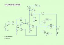
I'm not sure what level of detail you need. Here's a very simplified schematic made with LT Spice. This should make the basic function much clearer.
The tricky thing with the simulation is that the "current dumping" transistors Q3 & Q4) are normally off. In a frequency domain simulation they will not play a role. So a time domain simulation is needed OR you need to add some artificial bias to the current dumpers.
Brian
Attachments
Thank you Traderbahn... i'm needing detailed description
I have found other threads, and i have found current limiters and also voltage limiters.... this is not a very good idea but could not understand the reason why they have used those subcircuits.
Also i have visited sites where they update and upgrade the Quad 405 and other Quad models.
Well... i am studying the unit... and i have made some tests years ago, but had never good results.
Trying once again...of course your schematic is helping a lot too.
I would like to have a detailed description we use to read when factories explain how the circuit operates..... i have made an example into the first post.
thank you,
regards,
Carlos
Keith Snook's homepage should not be forgotten. He also refers to Bernd Ludwig's document.
http://www.dc-daylight.ltd.uk/Valve-Audio-Interest/QUAD/QUAD-405-Modification/QUAD-405-Mods.html
http://www.dc-daylight.ltd.uk/Valve-Audio-Interest/QUAD/QUAD-405-Modification/QUAD-405-Mods.html
Re: Thank you Traderbahn... i'm needing detailed description
The output voltage limiters were used to protect the electrostatic speakers from destruction. After all the ESLs were Peter Walker's real claim to fame. The tube amps were okayish, the 303 and 405 a bit less so but always had a loyal following. The preamps were all dreadful, both tube and solid state. Peter Walker did not believe in audiophilia or that amps really sound different. Still, he designed some pretty amazing speakers.
destroyer X said:
also voltage limiters.... this is not a very good idea but could not understand the reason why they have used those subcircuits.
The output voltage limiters were used to protect the electrostatic speakers from destruction. After all the ESLs were Peter Walker's real claim to fame. The tube amps were okayish, the 303 and 405 a bit less so but always had a loyal following. The preamps were all dreadful, both tube and solid state. Peter Walker did not believe in audiophilia or that amps really sound different. Still, he designed some pretty amazing speakers.
I am already reading the link you have posted Gustavsson
Interesting that Analog sa..... and he made nice units not believing in audiophilia...and he have produced something said as "an amplifier that sounds different"..... interesting those things.
Imagine Einstein not believing in ligth speed and considering it as the maximum possible speed to travel.
thank you folks...i am enjoying to explore the amplifier......
I have found other threads too, and many links about.... i am already understanding much more.
So... limiters where there because of electrostatics...hmmmm..maybe we can remove them!
regards,
Carlos
- Status
- This old topic is closed. If you want to reopen this topic, contact a moderator using the "Report Post" button.
- Home
- Amplifiers
- Solid State
- Quad 405 - Can you describe how this circuit operates?