Hi all.
If you don't know about the Rush cascode I suggest you use Google and your other preferred resources to get some background information. Here are some threads and pages where it has been discussed:
http://www.4qdtec.com/pwramp.html
http://www.4qdtec.com/preamp.html
http://www.diyaudio.com/forums/showthread.php?threadid=61289
First of all, I need to add that I don't have much experience in electronic design. My comprehension and understanding at this point has come entirely from resources such as DIYAudio, Doug Self's site and many other free internet resources. Even though comprehension has come relatively easy for me, everything I know has still come from theoretical sources and not true time-tempered experience.
The Rush Cascode is a manifestation of the differential long-tailed pair. Same concept, different ways to implement it. It was first used by englishman Christopher Rush of THX fame, who is still designing today (info provided by AKSA).
In some posts here on DIYAudio, the Rush cascode has been dismissed quickly after theoretical and mental comparisons to the conventional long-tailed pair (henceforth referred to as the LTP) as an input scheme. I think more thought and work should be put into its understanding.
The Rush cascode can be difficult to get working because of its speed and gain, not to mention DC offset and temperature compensation if one intends to make a DC-coupled amplifier. However, there are things we can do to get around this, which I intend to expand upon.
The rush cascode can be difficult to make stable for the following reasons:
1: High gain.
2: High speed.
The common solutions to this are:
1: A degeneration resistor between the emitters to decrease gain.
Firstly, it seems there is a misconception that like the conventional LTP, the Rush Cascode benefits from using high-gain transistors. In my simulations I have found this to be inaccurate.
I have the following observations to present:
1: The distortion of the Rush Cascode is more dependent on the degeneration resistor than it is the transistors used. A low degeneration resistor will in my experience get lower distortion.
2: Stability decreases with higher-gain transistors.
I have the following suggestions when implementing the Rush Cascode:
1: Use low-gain devices, like the 2N5771/5769, with as small a degeneration resistor as possible.
2: Increase open-loop gain in other parts of the circuit instead of the cascode itself. This will result in better stability and distortion than the other way around.
3: Use both legs, rather than one, to increase OLG and VAS speed.
I believe that the Rush Cascode should have some 'net coverage, which is why I am doing this. More people should know about it.
So I want to make a Wiki page and/or PDF that talks about it along with some example circuits. I also have designed and amp on the sim that has a nifty thermal and DC offset compensation scheme, although it requires some calculations.
I want to see more circuits with it, and I want to see how others get past its shortcomings.
Attached are some ways I have used it in the simulator.
- keantoken
Attachments
Rush Cascode
Great initiative collecting info on the "Rush Cascode" Keantoken!
I took some time trying to find more information about this intriguing circuit and will just add it here for any ones information, first of this sweet child seems to have a few names, some controversial or used in other type of transistor circuitry, which are:
* Rush Cascode
* Complimentary LTP (Long-Tailed Pair) (However, this name applies as well to ordinary LTP's, eg. two LTP's, where one is N-channel LTP and the other a matching P-channel LTP, used together)
forr, a user here on DiyA thinks it's called:
* Series Differential Pair (renders very meager search engine result, but a suitable name indeed, or how about Vertical Diff Pair, VDP)
* Emitter Coupled Pair (this is incorrect as it is another name for LTP, see -> https://wiki.analog.com/university/courses/electronics/text/chapter-12 )
forrs' comment: http://www.diyaudio.com/forums/solid-state/239365-emitter-follower-vas-stage-new.html#post3564984
And adds "I think it was used in an Akaï amplifier around 1980."
I tried to search anything related to Rush Cascode + Akai but didn't find anything.
An odd search engine collecting "key-phrases" gave the following result
"Cascode" related terms, short phrases and links
"AKSA John, My understanding is that it is a Rush Cascode, discovered by Christopher Rush, I believe an Englishman, in 1964."
I assume due to the nature of operation of the Rush Cascode, the type of distortion is leaning towards even harmonics,
perhaps someone could fill in more here on the Rush Cascode characteristics.
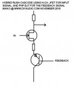
Also, a Rush Cascode could probably be made up of a hybrid mix of different types of gain devices, for instance a N-ch JFET input, and a PNP BJT for the feed back.
-------------------
ps. Attaching some of the schematics from the links' Keantoken gave in case those web pages would ever disappear.
pic.1 4QD-TEC: Low distortion Audio amplifier
4QD-TEC: Electronics Circuits Reference Archive
Low distortion (0.02%) audio amplifier, circuit is dated January 1977
pic. 2 4QD-TEC: Audio preamplifier circuits
Simple to use it as a low impedance mic amp or as a high input impedance preamp for mic or, with a suitable RIAA equalization, for phono pickup or similar.
pic. 3 https://mrevil.asvachin.eu/amp/topologies/rush/
A simple Rush Cascode input stage
TOP
Great initiative collecting info on the "Rush Cascode" Keantoken!
I took some time trying to find more information about this intriguing circuit and will just add it here for any ones information, first of this sweet child seems to have a few names, some controversial or used in other type of transistor circuitry, which are:
* Rush Cascode
* Complimentary LTP (Long-Tailed Pair) (However, this name applies as well to ordinary LTP's, eg. two LTP's, where one is N-channel LTP and the other a matching P-channel LTP, used together)
forr, a user here on DiyA thinks it's called:
* Series Differential Pair (renders very meager search engine result, but a suitable name indeed, or how about Vertical Diff Pair, VDP)
* Emitter Coupled Pair (this is incorrect as it is another name for LTP, see -> https://wiki.analog.com/university/courses/electronics/text/chapter-12 )
forrs' comment: http://www.diyaudio.com/forums/solid-state/239365-emitter-follower-vas-stage-new.html#post3564984
And adds "I think it was used in an Akaï amplifier around 1980."
I tried to search anything related to Rush Cascode + Akai but didn't find anything.
An odd search engine collecting "key-phrases" gave the following result
"Cascode" related terms, short phrases and links
"AKSA John, My understanding is that it is a Rush Cascode, discovered by Christopher Rush, I believe an Englishman, in 1964."
I assume due to the nature of operation of the Rush Cascode, the type of distortion is leaning towards even harmonics,
perhaps someone could fill in more here on the Rush Cascode characteristics.
Also, a Rush Cascode could probably be made up of a hybrid mix of different types of gain devices, for instance a N-ch JFET input, and a PNP BJT for the feed back.
-------------------
ps. Attaching some of the schematics from the links' Keantoken gave in case those web pages would ever disappear.
pic.1 4QD-TEC: Low distortion Audio amplifier
4QD-TEC: Electronics Circuits Reference Archive
Low distortion (0.02%) audio amplifier, circuit is dated January 1977
pic. 2 4QD-TEC: Audio preamplifier circuits
Simple to use it as a low impedance mic amp or as a high input impedance preamp for mic or, with a suitable RIAA equalization, for phono pickup or similar.
pic. 3 https://mrevil.asvachin.eu/amp/topologies/rush/
A simple Rush Cascode input stage
TOP
Attachments
Last edited:
Ha, that was almost 8 years ago. Of course I never got around to the wiki page. Since then DIYaudio has learned quite a lot about this circuit. A dual complimentary version has been used in CFA amps.
At some point someone suggested we call it the NTP, No Tail Pair. Most people here could figure out what you meant if you called it a Rush Cascode, although that isn't really accurate.
I suspect the main reason it hasn't caught on in the current generation of super-amps inspired by OStripper and the CFA group, is because it's asymmetric behavior isn't conducive to super-clean square waves. A dual symmetric version has been used to get around this problem.
It can also be more stressful to use, since it can have latching problems and overload issues can be tricky to solve.
A quick schematic of the hybrid proposal, will it work?")
I think I've seen this in app notes and phono preamps. It will certainly work, if used correctly.
A quick schematic of the hybrid proposal, will it work?
Yes, it will work...and current setting resistor between source and emitter may not be needed.
I found this in a 1967 book, unattributed. Sadly I can't remember which book, don't have a scan. I did a write-up of a mike-amp working this way, but web-rot has lost the images. I recently dreamed-up a fully "push-pull" complementary form with diff-output, sim-verified, but I don't think the world wants it.
Yes, even my apparently "push-pull" form really works push-push. All even-order nonlinearities up to clipping.
Many ways to skin cats.(*) You can always stitch-up skins into a coat. As far as I see, this way leads to lop-sided coats. You can tug and pull. Or you can skin the cat symmetrically, get a symmetric coat shell, and "lop side" it with snips and trims. (*I do NOT endorse cat skinning!! It's just an old american saying.)
Attachments
Last edited:
Patent US 3578911 uses the topology. The application is odd by audiophile conventions. The input and the output are the same. This connects directly across an existing (and long and installed) audio line. It makes a negative capacitor which sucks-out the capacitance in a line. Further, telephone line-center power supplies are much higher than signal voltages. The topology "stacks" two 24V amplifiers on one 48V supply.
Attachments
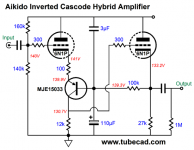
Updating this thread with more Rush hybrids mixed with tubes.
The Inverted Cascode
Attached an example from Tubecad, voltage supply is 300 V for this circuit.
The Inverted Cascode
Attached an example from Tubecad, voltage supply is 300 V for this circuit.
Attachments
Hi all.
In some posts here on DIYAudio, the Rush cascode has been dismissed quickly after theoretical and mental comparisons to the conventional long-tailed pair (henceforth referred to as the LTP) as an input scheme. I think more thought and work should be put into its understanding.
The Rush cascode can be difficult to get working because of its speed and gain, not to mention DC offset and temperature compensation if one intends to make a DC-coupled amplifier. However, there are things we can do to get around this, which I intend to expand upon. - keantoken
This cascode variation I know since a long time, but until now I don't know the right naming of this topology (in German we call it "emitter coupled cascode").
Are there papers or amplifier books from Mr. Christopher Rush concerning this topology ?
Thanks for an advice.
Some URLs:
https://www.diyaudio.com/forums/sol...e-input-amp-vs-ltp-input-amp.html#post6516692
Mr Evil's Realm - Rush Cascode Input Stage
4QD-TEC: Low distortion Audio amplifier
Input stage idea (#25+26)
Mr Evil's Realm - Rush Cascode Input Stage
Input stage idea
(#25)
The sound of cascodes (#66)
Thank you for those links, that is better documentation.
When used in a VAS, we can call it a Rush Cascode because the effect on the driving transistor is as being cascoded (just with the emitter and collector swapped).
When used as a differential stage we can call it an emitter-coupled differential, an emitter-coupled pair, or (my favorite) a No-Tail-Pair or NTP. Maybe even a Rush pair.
But lest we get too pedantic, remember that in an inverting amp configuration, it resembles a cascode again with one transistor in common base configuration. Also consider that even a single transistor could be considered a differential, as in a singleton amplifier topology, so we have every right to call a common-emitter VAS a differential amplifier. When we give something a name we are not so much describing what it is, but what it's purpose is to us. That's why we call it a VAS and not a differential.
One main problem here is that the only name that sticks is the one that everyone can remember. The names I remember are Rush Cascode, and No-tail-pair (because I came up with that one, go figure). The Sziklai patent in 1959 quite authoritatively however dons it "emitter-coupled pair". So is it then that the truth been known since 1959 and we poor fools are just too proud to submit to a higher authority?
Have I thoroughly ruined every possible name yet?
Transistors and tubes are fundamentally differential devices.Also consider that even a single transistor could be considered a differential
A transistor at the same operating point has the same sensitivity to emitter current no matter what circuit it is used in. You must mean something else.
I think we are allowed to break up the Rush pair into it's individual parts rather than treating it as a whole stage. You can analyze it as a common-base transistor coupled to a common-collector transistor. The math doesn't care which one or where you draw the borders. Each competing description would simply solve the equation differently. Only humans care... Reality is waiting on the bench as we argue about it.
There is no one "true" description of a circuit any more than there is "one true dictionary", with all other dictionaries being false. That is why as engineers we design a circuit by solving equations, not by seeing which names sound better together.
In a Rush circuit where one base is grounded, the current through that transistor is determined by the voltage across it's base-emitter junction. That voltage so happens to then be determined by the voltage across the other transistor's base-emitter junction.
So then you cannot call it common-base because you terminate the chain of causality at the other base, rather than at the emitter. However not all of us break up circuitry this way, nor is there reason we all ought to think the same way.
If the base of that transistor is grounded, in the case of an inverting amp Rush differential or a Rush cascode used as a VAS, then that transistor meets all criteria to be considered in common base configuration. The criteria is: the base is a common, the emitter is the input and the collector is the output.
Hi Hugh,A rush cascode is just an emitter follower driving a common base VAS. Since the two devices pass the same current, the impedances of the output of the EF and input of the CB are identical and it produces dominant H2 and H4.
I disagree that one transistor of a Rush circuit can be in a common base mode.
In a common base mode, the current through the transistor is almost insensitive to the bias of the base.
In a Rush circuit, the current through each transistor is determined by the voltage between the two bases. This makes it a differential circuit.
A cascode is not a differential circuit.
I notice you deleted the post I replied to in order to correct a mistake. I was confused for a bit.
This depends what the emitter is connected to, which is nowhere given in the description of a common base stage. The common base configuration does not assume, for instance, that the emitter will be connected to the collector of another transistor. If that were the case you would be right. But what if it happens to be connected to another emitter? It becomes sensitive to base bias, but by the rules we still call it a common base configuration.
Cascode and differential are just two ways we have of interpreting a circuit. They just describe what purpose it has to us. In some circuits we could call the Rush pair a cascode because while it could be logically understood as either a cascode or a differential, it's purpose to us is as a cascode.
Imagine an inverting amplifier where the the Rush pair has one base grounded, and the collector feeds the VAS. It's hardly a stretch to call the transistor with the grounded base a cascode, or a common-base transistor. We could even see it as a virtual ground for the emitter of a singleton input stage.
It's not wrong, the analysis following from that description will not be incorrect. And since correct predictions of circuit behavior are the goal of circuit analysis, what we choose to call a circuit or how we break it up is up to us as long as it leads to a correct prediction.
In a common base mode, the current through the transistor is almost insensitive to the bias of the base.
This depends what the emitter is connected to, which is nowhere given in the description of a common base stage. The common base configuration does not assume, for instance, that the emitter will be connected to the collector of another transistor. If that were the case you would be right. But what if it happens to be connected to another emitter? It becomes sensitive to base bias, but by the rules we still call it a common base configuration.
In a Rush circuit, the current through each transistor is determined by the voltage between the two bases. This makes it a differential circuit.
A cascode is not a differential circuit.
Cascode and differential are just two ways we have of interpreting a circuit. They just describe what purpose it has to us. In some circuits we could call the Rush pair a cascode because while it could be logically understood as either a cascode or a differential, it's purpose to us is as a cascode.
Imagine an inverting amplifier where the the Rush pair has one base grounded, and the collector feeds the VAS. It's hardly a stretch to call the transistor with the grounded base a cascode, or a common-base transistor. We could even see it as a virtual ground for the emitter of a singleton input stage.
It's not wrong, the analysis following from that description will not be incorrect. And since correct predictions of circuit behavior are the goal of circuit analysis, what we choose to call a circuit or how we break it up is up to us as long as it leads to a correct prediction.
Last edited:
Rush Cascode Input/VAS
I have used the `Rush Cascode' (and I know it's not really a cascode - but that's what it's usually called) in a few amplifiers, and I think it is a very useful circuit.
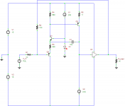
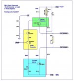
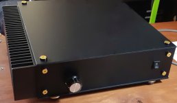
Recently I built a small 60 watt amplifier (called PB10) that uses a Rush Cascode to produce a balanced VAS drive - see the attached concept drawing. I use both sides of the Rush Cascode (yellow) to drive a folded cascode (green) on one side and a current mirror (blue) on the other side. The input was a simple gain stage, and a dual die lateral mosfet output stage, with no overall feedback. A picture of the finished amp is attached.
I find the advantage of the Rush Cascode is that it is strongly second harmonic dominant, and has very low odd harmonics, which is what I like. The PB10 amp is about 0.005% THD and H2 dominant at all frequencies and power levels, which is what I was aiming for.
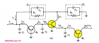
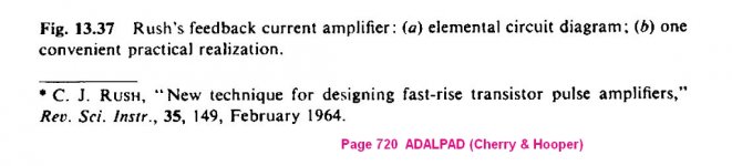
I have some vague memories of Ed Cherry taking about Rush Cascodes, so I went looking in ADALPAD (Cherry & Hooper book), and found some references on page 720 - see attachments.
Paul Bysouth
I have used the `Rush Cascode' (and I know it's not really a cascode - but that's what it's usually called) in a few amplifiers, and I think it is a very useful circuit.
Recently I built a small 60 watt amplifier (called PB10) that uses a Rush Cascode to produce a balanced VAS drive - see the attached concept drawing. I use both sides of the Rush Cascode (yellow) to drive a folded cascode (green) on one side and a current mirror (blue) on the other side. The input was a simple gain stage, and a dual die lateral mosfet output stage, with no overall feedback. A picture of the finished amp is attached.
I find the advantage of the Rush Cascode is that it is strongly second harmonic dominant, and has very low odd harmonics, which is what I like. The PB10 amp is about 0.005% THD and H2 dominant at all frequencies and power levels, which is what I was aiming for.
I have some vague memories of Ed Cherry taking about Rush Cascodes, so I went looking in ADALPAD (Cherry & Hooper book), and found some references on page 720 - see attachments.
Paul Bysouth
Attachments
The Sziklai patent in 1959 quite authoritatively however dons it "emitter-coupled pair". So is it then that the truth been known since 1959 and we poor fools are just too proud to submit to a higher authority?
I came through my electrical engineering degrees hearing this called an emitter coupled pair, and I was first introduced as the input stage of a LM741 op amp. There, it is used differentially and as a composite transistor wired as an LTP (long-tailed pair--I hate that name for a differential pair).
The reason (and this is the general reason for ALL weird topologies in early op amps) is that the IC processes severely limited the quality of the transistors on the chip. In LM741 days, the PNP transistors were absolute crap (low, low gain), so you could not use one for the input pair, nor for the VAS. In the LM741 scheme, the emitter-coupled pair makes for a NPN input (high beta) that acts like a PNP. Then, a high-beta NPN can also be used for the VAS transistor.
So, bottom-line, it's an emitter coupled pair.
- Home
- Amplifiers
- Solid State
- The Rush Cascode: Possible Wiki page