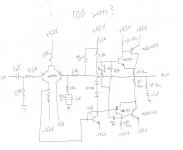
The Vbe multiplier is ineffective due to the limiting effect of the two series diodes.
That 1.2V to 1.3 volts will probably bias the amp into ClassB
Do not put the wiper of the vbe multipler to the base of the transistor. If the wiper goes open circuit it can lead to a blown output stage and that in turn could blow your speaker.
One pair of robust output devices can give 100W into 8r0 using ~+_50Vdc.
But to get 100W from the +-42Vdc requires one to use 4r0. This is asking too much from one pair of small output devices.
AndrewT said:
One pair of robust output devices can give 100W into 8r0 using ~+_50Vdc.
But to get 100W from the +-42Vdc requires one to use 4r0. This is asking too much from one pair of small output devices.
42 Volt rails.
50 Watt into 8 Ohm, yes.
For 100 Watt at least 45 and probably like AndrewT suggest 50 Volt
(40x40) / (2x8) = 100 Watt into 8 Ohm
where 40 is the peak voltage from supply.
Your drawn amplifier will work even if it is very basic.
There is nothing wrong with your circuit in schematic.
")
Just buy an AKSA amp
AKSA is $$$$.. I think trill wants something economical.
DX amp with 2 pair OP devices or my Frugalamp 1 would
do 4 ohms nice..
Or Quasi NMOS.. all these amps have support, PCB work
and cost 25-50$ (not including power supply) as well
as using very common devices..
OS
Hi Rtill
Andrew wt is right though the collector to base resistance should be fixed leaving the emitter to base the side which should contain the wiper so if it were to fail open bias would drop to zero thus saving the output devices. The diodes need to be yanked out too in paralell with the VBE multiplier. For a first amplifier for DIY I would recommend using the EFII darlington output stage rather than the Sziklai shown in your schematic they can be a PITA to get stable and turn off spikes can be horrid at crossover if underbiased that 150pf cap on the negative rail pair will kill the sonics and suck the life out of this stage which in turn will make the EFII a much more sonically desireable prospect. In a Sziklai output like shown the predriver needs to be fast with a high ft atleast double the ft of the driver device to avoid this cap even then turn off can get nasty, this pair is much better suited to Class A operation though inefficient in that respect.
Colin
AndrewT said:but extracting 100W into 4ohms is more onerous than 100W into 8ohms.
One pair will struggle to deliver into a 4ohm load.
if I add another pair of output tranistors, would this ease up the strain on the one pair?
AndrewT said:The Vbe multiplier is ineffective due to the limiting effect of the two series diodes.
That 1.2V to 1.3 volts will probably bias the amp into ClassB
Do not put the wiper of the vbe multipler to the base of the transistor. If the wiper goes open circuit it can lead to a blown output stage and that in turn could blow your speaker.
That might be the reason for the diodes - as backup in case the Vbe mult fails or is accicentally biased too high on the bench. In that case, use three diodes. It will be biased high if/when it does, but it will likely save it if you notice the overheating and shut down in time.
rtill said:
if I add another pair of output tranistors, would this ease up the strain on the one pair?
I thought that was the purpose of adding output pairs. If one pair does 8 ohms, two does 4 ohms, and four pair does 2 ohms.
2 pair will do real good on 4R.would this ease up the strain on the one pair
This was good advice , when I built my first ones (amps)I would recommend using the EFII darlington output stage rather than the Sziklai shown in your schematic
this topology proved "bulletproof" and being so typical ,
a lot of good advice can be obtained if you have problems.
I have the board work for a "universal" EF2 stage ,where you
can go bootstrap or CCS (2 pairs already working) 40-60v
scalable..
http://71.203.202.56/pdf1/Electronics/Projects/Audio_amp/Frugalamp/FA1_AB_4IN1_FULL.pdf
(note jumpers on Q3/4 and 8 , that's how you make the input stage like yours.) C(b)and R16 (a/b) is bootstrap config.
Also, if you are strapped for cash, ANY to-3p or flat BJT can be used. (njw0281- 0302 = $1.40 at mouser.)
EDIT .. on this amp if wiper fails on Vbe amp goes way underbias.
OS
Attachments
ostripper said:
EDIT .. on this amp if wiper fails on Vbe amp goes way underbias.
OS
I'd be more worried about wires to the vbe mult getting broken if it's mounted on a remote heat sink or directly to the power transistor case. Then it goes open no matter where the pot is set.
I don't know about just "any" flat pack. TIP33/34 or 35/36 would at least need to be graded for voltage before using them.
I'd be more worried about wires to the vbe mult getting broken if it's mounted
If you know how to solder and put 1/8" heatshrink around Vbe
leads this is a non-issue. the reason for wires is greater response
to thermal co-effecient vbe mount right on one of the OP
devices.
(Earlier version of the new pcb) I blobbed a little contact cement
where leads attach to board. this board is now almost 1 year old
used daily, absolutely no issues long term. $600 ASKA amps use same method. You are in texas, why mess with TIP's they are junk, Mouser is in your "backyard" (2$ shipping UPS)
OP trannies I've used mjl21193/4 , njl0281/0302 , you can even
use IRF9240/240 with different R17-19 ratio (VFET amp).
OS
ostripper said:You are in texas, why mess with TIP's they are junk, Mouser is in your "backyard" (2$ shipping UPS)
OS
Mouser isn't in everyone's backyard. Some builders would need to use whatever they have/can get. And not every project has equal weight. And with my own projects, I save the MLJ's for more serious projects where they are really needed. Like the 4kW monsters. I have mountains of TIPs, 2N type TO-3's, 140V Jap types looking for homes. And when I'm doing a project or weekend experiment where they will do, I use them.
What's the purpose of the 150pF cap on the lower driver?
Hi folks. Could someone read me a short lesson on the purpose of that 150pF cap on the driver of the lower output pair. I know its there for stability compensation, but since there isn't a corresponding cap on the top side, I'm wondering if it's there to address parasitic oscillation observed only in the bottom half cycles.
Because the collector of that driver doesn't swing much voltage, there isn't much Miller effect to take advantage of, so it just looked a little out of place to me.
This amp appears to be a derivation of one of the ESP designs, as noted earlier, and I see the same cap on the ESP website.
thanks,
Mike
- Status
- This old topic is closed. If you want to reopen this topic, contact a moderator using the "Report Post" button.
- Home
- Amplifiers
- Solid State
- will this work