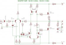
I'm working on another mosfet power amp...I have 1 question in regards to it. C1 is a 2.2 uf cap, however, all I have is a 2.2uf electrolytic. Can I use this and if I can, which way does + face? towards the circuit or towards the input?
http://www.elecfree.com/electronic/basic-mosfet-amplifier-100w-with-2sk15302sj201/
http://www.elecfree.com/electronic/basic-mosfet-amplifier-100w-with-2sk15302sj201/
In reality I dont think it really matters...But , since your CCS
is on the positive rail the bases of your LTP will be + 20-40mv.
so + on the EL would go toward the base of the tranny.
All of my DIY amps have CCS negative, and I have used
bipolar and polarized EL with + facing input.
Worst case the reverse voltage would only be 20-40mv
unless the CCS or differential failed.
OS
http://www.elecfree.com/electronic/...-2sk15302sj201/
I looked at the amp, and they list both vertical (IRFp's) and lateral
mosfets (2sj162/sk1058).
With the verticals they fail to mention that you need
thermal compensation and you would most likely encounter
problems if you used the IRFP's with that circuit.
A simple mje340/bd139 Vbias circuit replacing P2 would
be the preferred setup for the IRFP's.
Os
Hi,
with R3 from 330r to 470r, the VAS stage runs ~ 12mA to 15mA in each half.
I would drop R3 (150r to 200r) to increase the current in the LTP, add 200r Emitter resistors to the LTP and then drastically reduce the 3k9 collector loads to get the VAS stage down <=10mA per half.
But, whoever specified those output FETs does not know what he/she is doing.
I would not rely on anything he has posted if he makes fundamental mistakes like that.
The bases of the LTP sit positive relative to signal ground when idle.
They swing +- slightly when signal is present.
The positive voltage determines the direction of both the input cap and the NFB cap.
The value of this positive voltage is determined by the input offset current times {R1 + R2} resistor values.
Input offset current ~ LTP half current / hFE of the input transistors at that current.
R27 should match 47k + 2k2 i.e 49k2 (not 27k) for minimum output offset voltage, if the hFE of both LTP transistors are matched at the same Vbe and stage currents.
Slight alterations of R1 will precisely set the output offset to near Zero Volts. But unequal currents or unmatched transistors in the LTP will cause drift in output offset. The more accurate the matching of both devices and balancing of currents the less will the output offset drift with operational conditions. It will also sound better.
Find a better schematic.
rtill said:so...after reading your replies... this won't work?
Not likely for very long. If you look at FIG 7 in the datasheet for IRF240, you will see the transfer characteristics for 3 different temperatures. The zero temperature coefficient bias point is at 14A or so. Unless you set your bias to 14A, you will have bias drift. So if your bias is 200mA, you can see that as temperature increases, the required Vgs vs conductance decreases. If your bias doesn't have thermal compensation, you will have run-away.


However, if you look at the same transfer figure for a lateral fet like a 2SK1058 you will see the zero temp co point is 100mA, which means they turn off as they get hotter and don't need compensation. Your circuit would require lateral fets for this reason.
this won't work? Is there a mosfet amp using the irfp240/irfp9240 pair someone could post?
there are the quasi amps..
http://www.diyaudio.com/forums/showthread.php?s=&threadid=43331
http://www.adam.com.au/cgpap/QuasiWeb/index.htm
These amps use all IRFP 240's ,N-channel,
Then there is my collection - 30+ amps.. assorted mosfet..
http://71.203.210.93/pdf1/Electronics/Projects/Audio_amp/Mosfet_25-1kw/
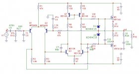
And the one I have working with BJT's now (schema is set for
IRFP 240/9240's , my next sub amp.. (see attachment)
OS
Attachments
Models are the same ,slightly different Vce..ostripper, isn't 2SA1837 the complement of 2SC4793, or have you deliberately got 1847
have to get the 1837 model.. I'm a perfectionist..thanks
by trill - ok...would this work
For a lateral mosfet Op, the sigma (see attachment) is
simple and I have SEEN the finished product. Many happy
constructors in serbia (thanks to Dr. jagodic).
For a Vertical solution(IRF), quasi's Nmos 200/350 (modified
for complimentary pairs) or quasi -complimentary (all N-channel)
is well documented and has been built by hundreds..
Go with something proven..parts are expensive,fires are
expensive.
OS
Attachments
You need to replace R6 with a VBE multiplier (or in this case, a VGS multiplier) - basically two resistors and a transistor.
Personally, I'd recommend you forget about this very basic circuit (from a Hitachi app note iirc, or at least based on it, designed for their LATERAL mosfets) and build Quasi's NMOS200 amp. It's good, stable and uses the parts you want.
Side note, one pair of TO-220 packaged MOSFETs is not enough for 55v rails. Either use two, or use something like IRFP260 in a TO-247 package.
Like Laycee and Ostripper said, build a circuit that already works, with adequate documentation. I tried to explain to you why the output stage would not work, and as a newbie, you should try to understand how the parts work fundamentally, and what the datasheets tell you before designing a circuit with them. I could have just said, "no it won't work" and left it at that, but that is a waste of time and space and is like telling you to go pi$$ up a rope. Of course if you don't want to undertake the effort to understand the fundamentals and just copy someone else’s work, that is just perfectly fine too. That might be your best route, maybe not. If so, there are some good fairly simple example circuits mentioned in this thread and you can search for more.
")
Good luck.
Of course if you don't want to undertake the effort to understand the fundamentals and just copy someone else’s work, that is just perfectly fine too. That might be your best route, maybe not. If so, there are some good fairly simple example circuits mentioned in this thread and you can search for more. Good luck.
rtill,
As CBS240 said, a stable circuit would be even more suitable.I'd start with a simpler circuit.
ostripper said:
And the one I have working with BJT's now (schema is set for
IRFP 240/9240's , my next sub amp.. (see attachment)
OS
The vBE multiplier has to be set to around 9-10 V.
For 2 reasons it may be best consider using one IRF610 mosfet for VBE:
1. Using one 0.7V BJT to set voltages more than like 5-6 Volts is not best approach.
Because of the high multiplication factor the precision is low.
2. Using one IRF MOSFET to compensate for IRF940/9240
means having very similar temperture behavior.
Nelson Pass has told us that the normal is to use BJT VBE for BJT Power Transistors.
And for HEXFET IRF Output we better use IRF VBE.
This gives also a lower multiplication factor.
Something around x2.
2 x 4.5 = 9 Volt.
re post9.rtill said:ok...would this work?
Vfets must have some type of temperature compensation, otherwise you risk Thermal Runaway and an expensive blowup that may also take out your speakers.
You must not swap to Vfets from Lfets. It just won't work.
Any design that omits temp comp is almost certainly exactly that a swap to save money because Lfets are expensive and Nchannel Vfets are very cheap.
ostripper said:
Then there is my collection - 30+ amps.. assorted mosfet..
http://71.203.210.93/pdf1/Electronics/Projects/Audio_amp/Mosfet_25-1kw/
And the one I have working with BJT's now (schema is set for
IRFP 240/9240's , my next sub amp.. (see attachment)
OS
I appreciate everyone's response. I am looking to try a simple amp that I could learn from and troubleshoot. I see in your list of amps you have built a 100 watt mosfet similar to the postings I previously posted. It uses 2sk1058/2js162 mosfets though....would this be a good one to try? Does it work well?
Attachments
- Status
- This old topic is closed. If you want to reopen this topic, contact a moderator using the "Report Post" button.
- Home
- Amplifiers
- Solid State
- cap polarity.... another mosfet amp