
mlloyd1 said:looks to make me think of the old big perreaux power amp.
what was it, the 5150 or something like that?
is the 220mv dc only (not low freq or high freq oscillations as verified on a scope)?
i might check if the electrolytic cap in the feedback leg is leaky.
mlloyd1
jacco vermeulen said:PMF5550
Very good guess mlloyd1 and jacco nailed it!
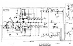
Sure enough this is the beastly Perreaux PMF5550.
Another boat anchor pulled from the "trash".
Now, before I get too deep into yet another big amp repair (the Rowland Model 7s I am repairing are still in progress), is this thing even worth fixing from a modern day performance perspective?
mlloyd1, I have only put a meter on the outputs so far and the AC voltage is very low in both channels (2mV).
I have only had a chance to clean it up (years of dust and cobwebs inside), check for any toasted parts, check the power supplies, etc.
Any ideas how to measure bias on this design with no source resistors?
Any idea what the correct bias current is for this amp?
Thanks!
Originally posted by ungie
Currently ~220mV offset on both channels. Any thoughts where to begin?
You should be able to adjust DC offset with RV2 pot.
Mike
You should be able to adjust DC offset with RV2 pot.
That is strange.., AC coupled offset adjust???
Does that use the ESR of the cap to affect the offset?
OS
ostripper said:
That is strange.., AC coupled offset adjust???
Does that use the ESR of the cap to affect the offset?
OS
Michael Chua said:Hi OS
It won't work with a cap as shown. It should be a resistor instead. Something like 47K.
Mike
I was thinking the same thing, but surely the same error could not have been made on more than one Perreaux schematic?
See this post for an identical DC offset arrangement:
http://www.diyaudio.com/forums/showthread.php?postid=895876#post895876
I should also note that I find it strange that both channels are showing a nearly identical high DC offset.
I will go through and check/replace all of the small electrolytics first to see if leakage is the issue.
jacco vermeulen said:The PMF models were biased in Class A to 10% of the nominal output level : 50W for the 5550, aka 2.5A, is 200mA per output device.
The current is measured at the rails.
jacco, you don't happen to have any service documentation for this or any other Perreaux amps of this vintage, do you?
I read in another thread about setting bias on these amps that the prodcedure is a little more involved than normal for setting DC offset and bias. Something about using an ammeter in place of the rail fuses, etc.
Thanks!
If there are no emitter resistors to measure the output stage bias, then solder 10r0 across the fuse holders in the supply rails. Tiny 1/8W or 1/4W resistors are ideal here. Leave them in permanently. They will blow with the fuses on abuse/overload/failure.
Remove the fuses and measure the volts drop across the 10r0.
This gives the quiescent current of the amplifier. Output bias current < amplifier quiescent current.
If the quiescent current >100mA then use 4r7 or 5r1 resistors.
Remove the fuses and measure the volts drop across the 10r0.
This gives the quiescent current of the amplifier. Output bias current < amplifier quiescent current.
If the quiescent current >100mA then use 4r7 or 5r1 resistors.
Originally posted by ungie
I was thinking the same thing, but surely the same error could not have been made on more than one Perreaux schematic?
That's a strange one. I don't see how having a cap there helps to adjust DC offset. Maybe some experts can enlighten us on this.
Originally posted by jacco vermeulen
The PMF models were biased in Class A to 10% of the nominal output level : 50W for the 5550, aka 2.5A, is 200mA per output device. The current is measured at the rails.
Originally posted by ungie
Something about using an ammeter in place of the rail fuses
If you decide not to use an ammeter, try to get hold of a 0.1 ohm Current Shunt. You would want as low a voltage drop as possible across the shunt resistor.
Mike
help please cause here i miss something
OK !!!! more or less everybody knows that my theory is not really enough .... but looking at this schematic there is a lot of things that i dont really understand ....
A)what about output resistors ..... amplifier i worked with (Legend4) didnt include any and all forum members were screaming about this ..... similar to this is the discusion about the JOY 200 amplifier ( an sziklai with 4 out transitors with out any out resistors ) so what's the catch here ????
B) since legend 4 was didnt include ccs in the vas or ltp stages was called a "POOR " design and not really stable as far as i can see from this schematic at least in the ltp stage there is no ccs here also . ......
C) can somebody tell me if this design is stable ???? then again how much power ???? and what is the rail voltage ...????
D) is this amplifier takes as a very strickt fact that outputs must be very well matched ????? or wtf is going on here ?????
answers please i am very confused now .....
C) can somebody tell me if this design is stable ???? then again how much power ???? and what is the rail voltage ...????
It is balanced , I have built/ simmed this topology and if properly laid out and compensated it CAN be very stable.. seems to run off
of +- 118 V rails
 and 113v for VAS/LPT. CCS would
be better for PSRR.
Outputs would have be matched.. A wire is very bad at
current sharing.. this is the same as the HH1200MX power amp
but a little more crude. (see attachment)
OS
Attachments
thanks OS
but your answers dont look really enough ......
what i mean is ....How come an amp like that runing at so much high rails doesnt requier CCS and out resistors ????
the circuit i was working with had only 4 mosfets and rails at max of 60 volts and i never managed to make it work propelry ( forum members also tryied to advice me but always we end up that deisgn is poor since dont have resistors vas and ltp without CCS )
what do you think that is the expected output of this amp ???? my calulation say that 500W is very possible given as a fact a very good psu ...am i correct ????
ITS NOT !!!!!
you have to look at the schematic again ..... its 12 outs totally but only 4 shown on the schematic ......
Stormrider said:+/-90Vdc on two pairs of TO3's ?!!!
you have to look at the schematic again ..... its 12 outs totally but only 4 shown on the schematic ......
- Status
- This old topic is closed. If you want to reopen this topic, contact a moderator using the "Report Post" button.
- Home
- Amplifiers
- Solid State
- An oldie. Maybe a goodie?