ostripper said:
That is strange.., AC coupled offset adjust???
Does that use the ESR of the cap to affect the offset?
OS
The cap is parallel with the pot and so will not effect the bias setting. It is there to help prevent oscillations.
Originally posted by sakis
A)what about output resistors ..... amplifier i worked with (Legend4) didnt include any and all forum members were screaming about this ..... similar to this is the discusion about the JOY 200 amplifier ( an sziklai with 4 out transitors with out any out resistors ) so what's the catch here ????
I believe you are referring to Source Resistors. For mosfet outputs, you can do away with source resistors but all the mosfets need to be tightly matched so that there's no current hogging.
B) since legend 4 was didnt include ccs in the vas or ltp stages was called a "POOR " design and not really stable as far as i can see from this schematic at least in the ltp stage there is no ccs here also . ......
CCS results in superior PSRR. Some designers prefer to use a resistor instead. I believe their reason is it sounds better.
C) can somebody tell me if this design is stable ???? then again how much power ???? and what is the rail voltage ...????
There is nothing fundamentally wrong with the design to render the amp unstable unless the compensation caps are of wrong values. Similar in design to my Lm60 (see below) except for power rails at 118V. At such high rail voltages, I would expect about 400W 8 ohms 1 kHz Sine.
What is surprising though is the current in the VAS. Its hard to make out in the schematic but if R12 is 240R, that would mean about 5mA per leg. That's a bit low to direct couple the mosfet current stage. This will result in early Slew Rate Limiting.
Mike
Attachments
Re: ITS NOT !!!!!
What schematic are you guys looking at? The one at the top of this thread clearly shows 12 output devices.
sakis said:
you have to look at the schematic again ..... its 12 outs totally but only 4 shown on the schematic ......
What schematic are you guys looking at? The one at the top of this thread clearly shows 12 output devices.
Originally posted by Steve Dunlap
The cap is parallel with the pot and so will not effect the bias setting. It is there to help prevent oscillations.
Hi Steve
I think you are looking at the wrong pot. Its not RV1 for biasing but RV2 that is supposed to be for DC offset adjustment. I don't see how that can work with C2 there.
Mike
RV1 sets the output bias.
RV2 is a horrible way to set the input offset to cancel output offset.
Could C2 be deliberately selected to be a leaky electrolytic?
Even matched Lfets require some source resistance to balance output current.
Is the 115Vdc on the voltage amp stage really so much higher than the 60.5Vdc on the output stage?
200mA through each Lfet and a total of 1.2A of FET bias. The designer must have been paying attention to Borbely.
Michael Chua said:
Hi Steve
I think you are looking at the wrong pot. Its not RV1 for biasing but RV2 that is supposed to be for DC offset adjustment. I don't see how that can work with C2 there.
Mike
You're right. I was looking at the bias pot. VR2 is not for DC offset adjustment. DC offset is handled by C4/C5 and no adjustment should be needed unless one or more of the caps has become leaky (as was mentioned earlier in the thread). VR2 appears to be feedback to improve PSRR.
Originally posted by AndrewT
Even matched Lfets require some source resistance to balance output current.
Hi Andrew
If the mosfets are well matched, you can do away with Source Resistors.
Is the 115Vdc on the voltage amp stage really so much higher than the 60.5Vdc on the output stage?
The output stage is at 118V. Voltage amp at 113V.
Mike
I have two pair of Sugden Lfet amps.
The two that were wrongly repaired now have 4pair of output devices.
I matched them. I selected Rsource (0r1) for matching as well, so that I could check the matching after assembly.
The FETs run at different idle currents and as a result different Tc temps and thus have different SOAR.
One device out of the 16 I had to match up is much worse than the others, I can feel the higher temperature. In effect this high temperature device sets the SOAR for the whole 4pair amplifier.
by andrew T. - schematic in post1 shows +60.5Vdc
I think the +- 60.5v is after the 47k's and is used only for the input bias trim. the mosfets run off the full rail.
Michael Chua said:If the mosfets are well matched, you can do away with Source Resistors.
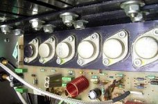
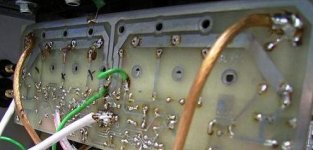
Goes for all Perreaux PMF models of that series, for example piccies of the PMF2150.
Top=>
Attachments
AndrewT said:I matched them. I selected Rsource (0r1) for matching as well, so that I could check the matching after assembly. The FETs run at different idle currents and as a result different Tc temps and thus have different SOAR. One device out of the 16 I had to match up is much worse than the others, I can feel the higher temperature. In effect this high temperature device sets the SOAR for the whole 4pair amplifier.
If the matching is correct, the mosfets should exhibit similar temperature. No Source resistors required. This is one of the main advantages mosfets have over bipolars. The other being able to direct couple to the VAS, thus doing away with the drivers and their interaction.
There was one instance when a customer complained some of the mosfets blew when he tested one of my big amps to full power. And this was with all matched mosfets.
Eventually, it was discovered that he did not apply thermal compound to the mica insulators. Once applied, problem solved.
Mike
The static killed them ?
The 80s fashion of restamping or making output devices incognito was pretty amusing, as if there was a vast array of different devices to pick from.
The PMF2150 came out a few years after the 1980 Hafler/Borbely DH-200, which didn't have source resistors either.
Afaik, Peter Perreaux started designing lateral MOSFET amps shortly after the 1977 Hitachi appl. note, doubtfull that he read Self and/or Borbely back then.
The 500W/8 PMF5550 cost serious money, it had a higher MSRP than a Threshold S/500, ML no23 or a Krell KSA-200.
Perreaux factory tour
(a variac, a DMM, and 2 sets of five resistors of 1Ohm/1W in parallel instead of the fuses should make it easy to set the bias)
- Status
- This old topic is closed. If you want to reopen this topic, contact a moderator using the "Report Post" button.
- Home
- Amplifiers
- Solid State
- An oldie. Maybe a goodie?