It will work both in theory and practice, using only ordinary refinements which are generally known to average practitioners of the art.
There's no difficulty in plugging in publicly-available models into SPICE and verifying the numbers claimed. You may also substitute other devices if you wish and examine the impact on distortion and stability.
There's no difficulty in plugging in publicly-available models into SPICE and verifying the numbers claimed. You may also substitute other devices if you wish and examine the impact on distortion and stability.
Hi Linuxguru,
as always some exotic designs from you...nice to see new way of thinking. I didn't simulated your circuit yet, but considering reaction you get from our fellow members maybe you should double check your models. Maybe they are too ideal or something else is wrong with simulation?
I will be back here later....
Cheers
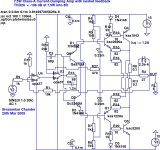
OK, here's a more practical version of the same topology, with lower rails (2 x 15v), lower quiescent current (1.2A), lower output power (7.5W into 8 ohms), and more garden-variety op-amps (opa37). There are changes to the biasing and gain, but the core concept remains the same. The gain of the inner loop had to be reduced to ~3 to stabilize it with the opa37, leading to higher distortion (as expected). However, the sonics may actually be preferable - it is closer to tube and vintage JLH sonics with a dominant H2 component at ~ -106 dB.
This also acts as a sanity check on the earlier simulation result - distortion is higher, as expected, but it still works and can be stabilized under different conditions with different devices.
This also acts as a sanity check on the earlier simulation result - distortion is higher, as expected, but it still works and can be stabilized under different conditions with different devices.
Attachments
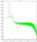
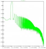
Now here's another simulated THD20 FFT, with everything being the same *except* that R13 (the resistive component of the bridge on the high-impedance side) has been removed entirely. This unbalances the bridge, but the topology is still stable (the point of this exercise is purely a simulation experiment, to demonstrate the impact of the feedforward component R13).
Result: H2 and even harmonics remain more or less the same within a few dB of the previous case (with a balanced reactive bridge). However, H3 and odd harmonics increase substantially: ~20 dB increase in H3 to around -95 dB from -115 dB.
Edit: This shows the possibility of having a switch (which switches R13 in and out of the bridge) to select sonics. With R13 out, the topology has typical solid-state sonics. With R13 in, the odd harmonics decrease by 20 dB or more, with little or no impact on the even harmonics; and the sonics become more tube-like.
Attachments
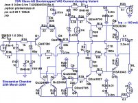
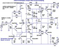
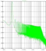
Here's a version of the same idea with Darlington output transistors operated in Class-B. This simplifies biasing, eliminates the Vbe multiplier, and reduces the possibility of thermal runaway. All components are bog-standard commodity components, including the output stage with industrial power darlingtons (easily substituted with TIP142/147 or similar). The VAS transistor can substituted with just about any low-Cob video or chroma transistor. The LTP-stage transistors can be substituted with BC550c/560c or equivalent.
The THD20 FFT in the middle shows the effect of feedforward - H2 dominates, and the first few odd harmonics are all ~20 dB below the previous even harmonic.
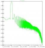
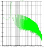
The THD20 FFT on the right shows what happens when the feed-forward resistance R20 is removed. H3 and the odd harmonics dominate, and the odd harmonics are nearly 40 dB higher than the previous case.
The THD20 FFT in the middle shows the effect of feedforward - H2 dominates, and the first few odd harmonics are all ~20 dB below the previous even harmonic.
The THD20 FFT on the right shows what happens when the feed-forward resistance R20 is removed. H3 and the odd harmonics dominate, and the odd harmonics are nearly 40 dB higher than the previous case.
Attachments
One can demonstrate with a bit of "higher maths it is impossible to completely correct the error caused by unbiased BJTs. Walker was wrong here als well the Hevreng analysis is wrong. It has nothing to do with the open loop gain of the class A. The error is that a function is treated as a constant. Quad does not make current dumping amps any more since 1999. Another point is that Spice simulations to achieve transient analysis are dead wrong for current dumping. The sim get only the h2 and h3 about right the rest is computed way too low. But this is not to say that current dumping amps are bad.
However they can be made very simple in topology because the circuit of predriver matters less then an exact computation of the bridge component ( there is an optimum one cannot choose any free ) and most important is the quality of the inductor.
Best is a very large former ( up to 10 cm diameter) and multiply stranded wire.
- Status
- This old topic is closed. If you want to reopen this topic, contact a moderator using the "Report Post" button.
- Home
- Amplifiers
- Solid State
- Current-dumping Class-AB Self Type-II EF O/P