
Good day. I have a JVC RX-5THPBK amplifier which the display is dead on. I started some time ago with dismantling and trying to find the problem. I have done many tests and measurements which I will include below in the message. I have attached 2 schemetic diagrams to have a look at.
Ok. This was my approach and information I found when testing:
1) Checked for any cracked / overheated transistors and diodes. - Nothing.
2) Checked for any dry joint on the power and display circuit. - Nothing
3) I assembled the the unit half way (letting out other circuits such as the tuner, dolby audio processor, etc. And I found after disconnecting the source input control board, the display worked again. So I connected it again. Dead
4) I then started to look for a possible short circuit. I removed some of the bridge wires on the source input source control board distributing power to other components and found the pin on the connecter that makes the display go dead. I replaced the other bridge wires not related to the problem. I was then left with 2 resistors and a bridge wire.
5) I then took the multi meter and measured the voltage when the 2 resistors and bridge wire is removed. I got -12V.
When the one resistor is in place: +1.5V and display is dead.
Then the second resistor on its own: -9V and the display dimmed.
Then the bridge wire on its own: +2V and display is dead.
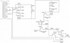
6) I drew then a schemetic to get a better understanding. - See the included schemetics. As seen in the schemetic there is a Pin 5 on CN851 this is what is supplying power to components of what I have tested above. I had a look at tose components receiving the power. It's a few OP Amps and 2 High Voltage Analog Function Switch Array (TC9212P).
7) I then soldered back those 2 resistors and bridge wire. And did the following tests:
Tested pin 1 on CN801 (F1) - Without input source control board: -8V. With board: +3.3V
Tested pin 2 on CN801 (F2) - Without board: -8V. With board: +3.3V
Tested pin 3 on CN801 (VPP) - Without board: -13.5V With board: +1.5V
8) I then removed all the diodes (D840, 841, 822 and 885) related to the circuit and tested them. Could not find any of them faulty. Then the transistors (Q841, Q821 and Q885) and could not find any problems on the transistors.
Thats all I have tried so far. Has anyone have suggestions? Thanks in advance.
Attachments
- Status
- This old topic is closed. If you want to reopen this topic, contact a moderator using the "Report Post" button.