Hi all,
I am in the process of repairing a PS Audio 200c. It's previous owner blew out one channel by accidentally shorting the outputs, internally disconnected the rails from that channel, and then later blew the other channel due to a bad biwire.
I haven't finished pulling everything yet. All the outputs I've found so far are shorted, and it looks like at least one of the driver pairs are shorted as well. This amp originally used NEC outputs, 2SD555's and 2SB600's. One channel had been repaired in the past with NSC(?) versions of these numbers. Anyway, since these devices are a bit scarce and highly counterfeited, I looked into subs. In the later version of this amp, the 200cx, PS Audio used MJ21193's and MJ21194's. I checked the datasheets and these looked like a pretty good sub; Paul McGowan was also kind enough to confirm that they should work fine.
So, at this point, I'm swapping out the blown outputs, drivers, and one burned resistor for sure. I am also planning to replace the on-board electrolytics. They are mostly Matsushitas, which I have found to be very long-lived and heat-resistant, but these are the 85 degree variety and they are over 20 years old as well. The stock filter caps actually still read about 17000uF on my Fluke (they're rated at 15000uF) but I'll probably upgrade/replace those once the rest of the amp is up and running. I also saw a post on audioreview.com where someone recommended replacing the original bridge rectifiers with FRED rectifiers. I would appreciate your thoughts on that suggestion.
Lastly, I have some questions about fuses for this amp. I know that the stock output fuses are supposed to be 8A (speaker protection, not rail). This seems a bit odd in that the amp is rated 400W continuous into 4 Ohms, and 800W continuous into 2 Ohms. Perhaps the manufacturer expected larger fuses to be installed when driving lower impedance loads? Also, the line fuse was a 5A slo-blo. This doesn't seem a likely value and I wonder if that's just something the PO swapped in at one point. I would have expected more like 12A+. Any ideas what it's supposed to be?
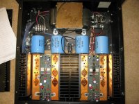
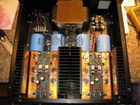
One other note: I saw another thread somewhere where someone repairing one of these mentioned that he didn't see any heat sink grease under the outputs. That degraded into a bit of back and forth about clear silicone grease, evaporation, new micas, etc. All of this was sort of out of place on that thread because these amps use copper bus bars to couple rail current from the filter caps to the output transistors. The cases are supposed to be connected to the copper, and the copper is, in turn, insulated from the rest of the heat sink. One question, though: is there any electrically conductive heat sink compound that could and/or should be applied here?
Thanks,
Paul
I am in the process of repairing a PS Audio 200c. It's previous owner blew out one channel by accidentally shorting the outputs, internally disconnected the rails from that channel, and then later blew the other channel due to a bad biwire.
I haven't finished pulling everything yet. All the outputs I've found so far are shorted, and it looks like at least one of the driver pairs are shorted as well. This amp originally used NEC outputs, 2SD555's and 2SB600's. One channel had been repaired in the past with NSC(?) versions of these numbers. Anyway, since these devices are a bit scarce and highly counterfeited, I looked into subs. In the later version of this amp, the 200cx, PS Audio used MJ21193's and MJ21194's. I checked the datasheets and these looked like a pretty good sub; Paul McGowan was also kind enough to confirm that they should work fine.
So, at this point, I'm swapping out the blown outputs, drivers, and one burned resistor for sure. I am also planning to replace the on-board electrolytics. They are mostly Matsushitas, which I have found to be very long-lived and heat-resistant, but these are the 85 degree variety and they are over 20 years old as well. The stock filter caps actually still read about 17000uF on my Fluke (they're rated at 15000uF) but I'll probably upgrade/replace those once the rest of the amp is up and running. I also saw a post on audioreview.com where someone recommended replacing the original bridge rectifiers with FRED rectifiers. I would appreciate your thoughts on that suggestion.
Lastly, I have some questions about fuses for this amp. I know that the stock output fuses are supposed to be 8A (speaker protection, not rail). This seems a bit odd in that the amp is rated 400W continuous into 4 Ohms, and 800W continuous into 2 Ohms. Perhaps the manufacturer expected larger fuses to be installed when driving lower impedance loads? Also, the line fuse was a 5A slo-blo. This doesn't seem a likely value and I wonder if that's just something the PO swapped in at one point. I would have expected more like 12A+. Any ideas what it's supposed to be?
One other note: I saw another thread somewhere where someone repairing one of these mentioned that he didn't see any heat sink grease under the outputs. That degraded into a bit of back and forth about clear silicone grease, evaporation, new micas, etc. All of this was sort of out of place on that thread because these amps use copper bus bars to couple rail current from the filter caps to the output transistors. The cases are supposed to be connected to the copper, and the copper is, in turn, insulated from the rest of the heat sink. One question, though: is there any electrically conductive heat sink compound that could and/or should be applied here?
Thanks,
Paul
A bit of an update: I think I've pulled all the blown parts now. Ironically, one of the NSC 2SB600's actually survived. Every other output was blown. The two PNP drivers were blown, but the two NPN ones survived - I think I'm going to swap all four anyway, just to be safe... they're only about $1 a piece.
On one side the bias transistors are OK, but on the other they're blown as well. These are the annoying ones (MPSU95 and MPSU45).
Anything else I should be looking at further back towards the input side of things?
Thanks,
Paul
On one side the bias transistors are OK, but on the other they're blown as well. These are the annoying ones (MPSU95 and MPSU45).
Anything else I should be looking at further back towards the input side of things?
Thanks,
Paul
One more update: parts are ordered! Most everything is coming from Mouser, except for the MPSU's which are from an eBay store.
One thing I noticed that I thought some of you might find interesting... these NSC 2SB600's have a base plate about half as thick as the original NEC 2SB600's. The NEC's also weigh (not surprisingly) about 30% more.
On the other hand, all the NEC's are dead, and one NSC lived to tell the tale... so either they are at least as good or they got lucky")
Cheers,
Paul
One thing I noticed that I thought some of you might find interesting... these NSC 2SB600's have a base plate about half as thick as the original NEC 2SB600's. The NEC's also weigh (not surprisingly) about 30% more.
On the other hand, all the NEC's are dead, and one NSC lived to tell the tale... so either they are at least as good or they got lucky
Cheers,
Paul
Got the Variac today and fired up the 200c. Looks like I didn't forget anything too important, as she started up just fine and responded well to adjustments of DC offset.
I also did a bit of quick testing with music and both channels sound OK.
In the process of setting bias now. I'm guessing about 100mA per device based on the published idle of 100W or so. Those heat sinks get decently warm at that bias. Still checking and waiting to see how thermally stable she is.
Two notes:
1. The bias pot might be opposite of what you'd expect - CW decreases bias, CCW increases it
2. That contactor (giant relay to provide on/off for the mains current) has to go - constant low level buzz!
Cheers,
Paul
Attachments
Pretty much done
Well, I did a bit more testing, and a bit of test listening. The amp drove my test speakers (Magnepan MMG's) very nicely indeed. I was surprised at how much bass it got out of them. During listening tests, at pretty good volume, I was constantly checking the bias and DC offset. I also tweaked the bias a bit when the amp was well warmed up, then checked it again after idling to make sure it was staying stable. It seems to rise a bit when driven hard, and the amp is definitely a bit underbiased when cold, but after about 20 minutes of idle it stabilizes and drifts back and forth within a 5mA per device window.
I was surprised, though, at the variation I see between these MJ21193's/94's that were part of the same manufacturing run. The biggest mismatch is among two of the NPN's in the right channel. With one biased to 120mA, its neighbor will only be pull 95mA or so.
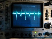
The bench testing included some sine waves from the function generator into 8 Ohm loads to check for any crossover notching on the 'scope. Looked good there.
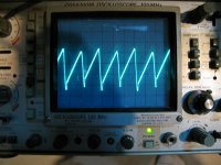
I also tried an about 100W 20Hz square wave with both channels driven into 4 Ohm loads. Main thing I was looking for there was whether I'd see any ripple on the tops and bottoms of the square wave... it was razor flat. I don't know if this a good test of the power supply caps, but I found it reassuring.
Lastly, I got a good scare, and a good indication of the current capability of the amp, when I first went to check the square wave output in the left channel. I had made load adaptors by wiring together two 8 Ohm 50W resistors with steel hookup wire about as thick as the leads of a 1W resistor; these I then attached directly to Pomona banana's for easy plugging in. Well, when I went to hook up the ground of my scope, I mistakenly attached it to the + out. I have two scopes, one with ground defeated and one that's grounded... this was the grounded one. The output from the amp instantly vaporized the steel wire between the plug and the resistors, but didn't seem to adversely affect the amp at all! Follow-up testing of that channel still looks fine.
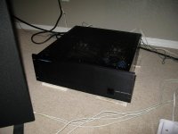
Here's a pic of the amp in its next install location, behind the Tympani IV's.
Well, I did a bit more testing, and a bit of test listening. The amp drove my test speakers (Magnepan MMG's) very nicely indeed. I was surprised at how much bass it got out of them. During listening tests, at pretty good volume, I was constantly checking the bias and DC offset. I also tweaked the bias a bit when the amp was well warmed up, then checked it again after idling to make sure it was staying stable. It seems to rise a bit when driven hard, and the amp is definitely a bit underbiased when cold, but after about 20 minutes of idle it stabilizes and drifts back and forth within a 5mA per device window.
I was surprised, though, at the variation I see between these MJ21193's/94's that were part of the same manufacturing run. The biggest mismatch is among two of the NPN's in the right channel. With one biased to 120mA, its neighbor will only be pull 95mA or so.
The bench testing included some sine waves from the function generator into 8 Ohm loads to check for any crossover notching on the 'scope. Looked good there.
I also tried an about 100W 20Hz square wave with both channels driven into 4 Ohm loads. Main thing I was looking for there was whether I'd see any ripple on the tops and bottoms of the square wave... it was razor flat. I don't know if this a good test of the power supply caps, but I found it reassuring.
Lastly, I got a good scare, and a good indication of the current capability of the amp, when I first went to check the square wave output in the left channel. I had made load adaptors by wiring together two 8 Ohm 50W resistors with steel hookup wire about as thick as the leads of a 1W resistor; these I then attached directly to Pomona banana's for easy plugging in. Well, when I went to hook up the ground of my scope, I mistakenly attached it to the + out. I have two scopes, one with ground defeated and one that's grounded... this was the grounded one. The output from the amp instantly vaporized the steel wire between the plug and the resistors, but didn't seem to adversely affect the amp at all! Follow-up testing of that channel still looks fine.
Here's a pic of the amp in its next install location, behind the Tympani IV's.
Attachments
Not ready yet
I installed the amp in my main system this evening, and, while it sounds decent, it's very noisy (idle background noise, not distortion). Part of that noise is because it's more sensitive than the Adcom GFA-555ii that it's supposed to be replacing, but a lot of the noise is coming from the amp itself.
Even with inputs disconnected, I am getting about 7mV A/C of noise from the left channel, which is pretty offensive through the Magnepan bass panels. The right channel is a bit better, at about 5mV. The Adcom, by comparison, is dead silent at idle. For now, I've put the Adcom back.
At idle, my meter shows about 50mV of ripple between supply rails and ground.
These are still the original filter caps, though all the other electrolytics are new. What do you guys think? Is this likely just tired filter caps or should I be looking elsewhere first?
What am I doing wrong here?!
Did I break some rules of etiquette or something with this thread?
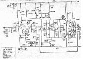
I see very vague posts with no details that get lots of traffic here. I have provided as much detail as I can (schematics, measurements, scope shots), and would be happy to provide more, as needed, but I can't get a single response.
I know there are people on this forum that know a lot more about this stuff than I do. Please take a moment to read the last couple of posts and give me your opinion of next steps.
Thanks,
Paul
Did I break some rules of etiquette or something with this thread?
I see very vague posts with no details that get lots of traffic here. I have provided as much detail as I can (schematics, measurements, scope shots), and would be happy to provide more, as needed, but I can't get a single response.
I know there are people on this forum that know a lot more about this stuff than I do. Please take a moment to read the last couple of posts and give me your opinion of next steps.
Thanks,
Paul
Hi Paul,
I have been following your thread closely and I am also at a loss with the lack of responses!
I am going through a very similar process at the moment with a pair of original Rowland Research Model 7 monoblocks.
It's strange how similar your experience has been so far.
My amps also use 555/600 output devices and a few were dead in one channel.
The other amp was working when I got it, but with some bias issues due to a faulty adjustment pot.
Now that that's fixed I am having the same issue as you with buzz/hum on the outputs. It's fairly low (4-7mV) but can easily be heard with no signal.
I have only just discovered this, so I have not had a chance to get a scope on it yet.
Could be due to old power supply caps, but I would also check the bridge/rectifiers to make sure everything is OK there.
I'll keep you posted on my progress and hope someone will give you some more input!
Hi Ungie,
Nice to know I'm not alone.
What did you do for replacement outputs for your Rowland? Did you sub them out, or did you find some original NEC's?
For mine, I think the next two steps will be: 1) Pull one of the caps and try to get an ESR measurement on it (I've being trying a tecnique with my function generator and a resistor that seems to work) and 2) try adding some small caps across the recifier diodes to see whether that helps the rail noise.
FWIW, I measured all the rectifiers diodes before I started repairing the amp, and they all measured fine. I don't know whether there are typical failure modes that would make them noisier without killing them, though. I also did a quick calculation of that noise relative to 1W (into 4 Ohms)... looks like mine, at about 7mV RMS noise, is -24dB from 1W. The original JLH amp was -70dB from 1W... so there's definitely a problem here.
On mine, should I need to replace the caps, I'm kind of hampered in that the physical size of the caps is quite critical. New ones could be shorter, or a little bit taller, but larger diameter won't work and smaller diameter probably won't work (due to fixed spacing of terminal attachment points). Most of the suitable value caps I'm finding are too long. The only two good-fit candidates I've found are GE's. I can either get exact value capacitance (15000uF) replacements at higher (90V) voltage for $38 each, or much higher capacitance (32000uF) at exact voltage (75V) for $33 each. My initial reaction, of course, is to go for the 32K's, but let's see how the ESR test goes.
Cheers,
Paul
Latest update:
I pulled one of the filter caps and tried my ESR test on it. I came up with an ESR of about 71 mOHMs, but my margin of error is probably pretty large. The real ESR may be quite a bit lower. I also read the capacitance out of circuit and, after about a minute, the Fluke had charged up to 14600... so a bit low, but well within tolerance.
I then put the cap back in, and tried removing the green/yellow ground wire from the chassis, to see whether ground noise in my wiring might be part of the problem. This didn't make a difference, but it seemed to me that the star grounding wasn't tight. I retightened it and rechecked the noise level. To my surprise, I was reading .4 mV from one channel and 2.4mV from the other. The noisy channel was still the noisy channel, but both channels were at least reading much quieter than before. Both get a bit noisier as the amp warms up, but not by too much.
I've been trying to trace down the differences in noise readings between the two circuits. With feedback and all, though, the noise seems to show up everywhere. I don't see any easy things to try next other than randomly switching components between the channels to see whether the noise switches as well.
I would appreciate any suggestions as to a less shotgun approach? Are these double J-Fets (NPD 5565) prone to noise issues? Should I disconnect the feedback loop to help isolate things? If so, where and how would be best? I did try opening removing the output fuses (since they're within the feedback loop)... this did not change the noise profile; however grounding the output (with the fuses out) raised the noise level on both channels.
Thanks,
Paul
Hi Paul --
[oops -- I wrote the below before reading your most recent post. Look at all other ground connections and wiring, even any soldered ones. And I'm even more convinced the noise is not from the dual fet.]
I'm the guy with the 2N5565s. I saw this thread earlier and finally caught on you're the same guy
I'm pretty sure this problem is not related to the input FET, and possibly not related to the caps. Have you checked all electrical connections, especially any grounds. A loose or bad ground connection in the bad channel could cause the noise problem you're having.
good luck
Phil
Hi,
As I have close to zero experience with fuses in rails and as speaker protection I can't say for sure, but I was told that fuses do not blow as one would naivly expect. So a 8A fuse does not blow immediately at 8A, but at - just to say any number here - 150% overload within 10s. Please read up the exact numbers in a datasheet.
So, given that music has a extremely high peak to average ratio, high current peaks are still easily possible while long term "protecting"* the amp.
Have fun, Hannes
PS: don't forget to read up the exact numbers!
PPS: *it's not really protective to act after severals seconds...Douglas Self reports in his book that in a test a woofer was blown within a second when the outputs hit the +40V rail
Lastly, I have some questions about fuses for this amp. I know that the stock output fuses are supposed to be 8A (speaker protection, not rail). This seems a bit odd in that the amp is rated 400W continuous into 4 Ohms, and 800W continuous into 2 Ohms.
As I have close to zero experience with fuses in rails and as speaker protection I can't say for sure, but I was told that fuses do not blow as one would naivly expect. So a 8A fuse does not blow immediately at 8A, but at - just to say any number here - 150% overload within 10s. Please read up the exact numbers in a datasheet.
So, given that music has a extremely high peak to average ratio, high current peaks are still easily possible while long term "protecting"* the amp.
Have fun, Hannes
PS: don't forget to read up the exact numbers!
PPS: *it's not really protective to act after severals seconds...Douglas Self reports in his book that in a test a woofer was blown within a second when the outputs hit the +40V rail
Spent a couple of hours this evening trying to find the source of the noise. I now know it's not the JFETs, nor the grounding scheme, but I still don't know what it is.
Unfortunately, while playing around with the DC offset adjustment to see whether some noise from that pot might be contributing, and also to see why the DC at the JFET sources didn't match between the two channels, I knocked together the collectors of two of the predrivers (2N6556) and blew one up.
Anyone know where I can get these things or what would be a good sub?
Thanks,
Paul
I looked through Mouser's parametric search and couldn't find anything that was a true match for a 2N6556. The specs on these are:
Vce 100V
Ic 1A
Pd 2W free standing or up to 10W heat sinked. Mine have little heat sinks on them.
fT 75 - 375Mhz
hFE @50ma 80-300
Cob 18pF
Sound to me like they might have been designed as CRT gun drivers, except that the 100V is a bit low for that.
Anyway, closest I found from Mouser were the Fairchild KSA1220's or KSA1220A's. They're lower power free-standing (1200mW), but rated 20W with heat sinks. Gain and bandwidth are comparable to the 2N6556's, but the Cob is almost double (26pF).
Thoughts? Anyone have any experience with these Fairchilds (Fairchildren?)?
Thanks,
Paul
P.S. Maybe, if I'm really lucky, one of these 2N6556's will have been the source of the noise.
I have a theory on where the noise is/was coming from (Phil, maybe this applies to your Rowlands as well).
What I realized, after smoking the predriver yesterday, was that the "noisy" channel was the one I had accidentally shorted earlier with the scope probe (Post #6). I doubt that's a coincidence, and the noise is obvious enough that I'm pretty sure I would have noticed it during the earlier listening testing I did.
What I think happened is that the current surge when I shorted the output, while it didn't destroy the outputs, did damage them, and the result is this 2mV noise.
Does this theory sound credible? Have any of you seen situations like this before? If so, was the damage confined to the drivers, or the outputs... both? other?
Phil, you mentioned that some of your output transistors were blown. I wonder if the other ones are 100%, or compromised.
Thanks,
Paul
P.S. I went ahead and ordered a bunch of the KSA1220A's, replacent resistors, a couple of TIP47's (just in case), and a whole set of drivers and outputs. Once I've got the front end repaired, I plan to swap in the driver and output parts bit by bit to see if/when the noise disappears.
Finally found the source of the noise!
Basically, one thing I was thinking about was that, since there was a DC servo and an offset adjustment for the input, I should probably disable the servo when adjusting the offset, so they wouldn't be fighting each other. I also thought that the servo might be the source of the noise. Well, after disconnecting the servo and checking the noise, I found that both channels were indeed quiet; the DC servo was the source of the noise.
So, I started troubleshooting the servo by reconnecting it and then checking resistances between the two channels to see what was different. I immediately noticed a difference between servo OUT to ground between the two channels. So, I started isolating things and pulling parts to narrow it down. Eventually I realized I was getting further from the difference rather than closer to it, so I started tracing back the other way, towards the JFET.
Things were definitely different down that end. What was different was the input resistor coupling the servo signal to the JFET. On the quiet channel it was 10K. On the noisy channel it was 1K! Not damaged, the wrong value!
Since I already had one of the TL-081’s out, I pulled the other one and swapped them, but I also installed a 10K in place of the 1K. Sure enough, upon firing it back up, both channels are quiet. I can’t believe anyone would have had a reason to replace that resistor after manufacturing. It’s not in a place that should have been damaged by anything, and the op amps were still original and matching batch numbers. At this point I’ve got to think that this thing left the factory with the wrong value resistor in there and had this noise all along.
Still need to place one more order to Mouser for a resistor that I blew earlier, and I'd like to get some longer legged KSA1220A's so that they will fit better on the board, but I think this thing is about ready for prime time.
Cheers,
Paul
- Status
- This old topic is closed. If you want to reopen this topic, contact a moderator using the "Report Post" button.
- Home
- Amplifiers
- Solid State
- PS Audio 200c repair and upgrade