Hi to all.
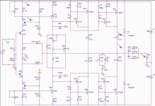
I made a schematic for an Amp (class AB or class A depents on biasing and supply) combining ideas from Nelson Pass F5 and Mosquito amps (first stage) and a litle bit strange symmetric output stage (a driver bjt for each output bjt). The output stage was tested in real circuit in the past with very good results).
The output DC is configurable and the bias can be altered through the vbe (bd139). The simulated Frequency response in pspice is exellent ( DC to 500 kHz).
Anyone wants to comment to the circuit is welcome. Do you think that it has potential?
thnx
Attachments

Thanks for the comments. The tips are just for simulation. I am planning to us MJE15034-34 MJL4281A (NPN) and MJL4302A (PNP). I used this compbination again with this kind of output stage and it was great.
When I tested this output stage (a drive bjt for each output bjt) in another amp I liked it to much. It was so warm like class A and tube sound. My impression any way. So I thought to combine two thinks that I like:
symmetrical fet input and this "strange output stage". I hope I will get something good.
As far as the bd 139 you are right, it is a mistake in this jpg.
Have you simulated the followings:
- OLG (open loop gain)
- phase response
- square wave response
- clipping performance
- stability with non cleary resistive (capacitive/inductive) loads
- IM (intermodulation distortion)
- THD
?
The frequency response alone tells almost nothing about an amplifier.
Cheers")
- OLG (open loop gain)
- phase response
- square wave response
- clipping performance
- stability with non cleary resistive (capacitive/inductive) loads
- IM (intermodulation distortion)
- THD
?
The frequency response alone tells almost nothing about an amplifier.
Cheers
kzeprf22 said:Do you think that it has potential?
Yes of course. Let us know how the real one turns out.
I've simmed a bunch of parallel devices before for an output stage but I've never tried paralleling multiple whole CFP's. You get points for uniquity.
Like has been suggested, good japanese VAS devices with good Hfe will increase open-loop gain and decrease distortion.
If you need SPICE models, just say the word. Of course, it helps to Google first...
- keantoken
Like has been suggested, good japanese VAS devices with good Hfe will increase open-loop gain and decrease distortion.
If you need SPICE models, just say the word. Of course, it helps to Google first...
- keantoken
Hi to All,
Mr Pass, thanks for the encouragement about this schematic.
Thanx for the points keantoken. This output stage really works and you you get real dynamic sound!. In fact my current AB amplifier has this stage. My current class A amp is F5 thats why I liked so much this FET symmetric input stage.
I will try to make a prototype (vector board), but as always happens it will take some time. If I have any news I will post.
Thanx.
After a long time I am back with this design.
I constructed one channel (resistor values changed from picture) but I have a problem that apparently I can not bypass. For tha VAS section I use ~10 ma I have jfets biased to ~7 ma and a vbe multiplier having ~0.7 volts between the collector and the emitter of the transistor used. The strange think is that I have a lot of bias current with this numbers at about ~300 ma. Is this normal. For output devices I used BD249 - 250 and 2SB817 - 2SD1047.
With the BD I have more current than the 2SB817 - 2SD1047. I done many tests ghanging many thinks but no lack.
At the beggining I had the 2SB817 - 2SD1047 and after test and try I managed the circuit to work without any problem (Iq =0), but now I can not get right. The think I changed is that I replaced the jfets from k246 to k170. Another symptom is that before not working at all It was a time were it wos working ok and after 2 minutes the current went up. Does anyone has any ideas?
Thanks
Fos vas I have 2sa1358 2sc3421
and for predriv 2SA1837 2SC4793
kzeprf22,
if you insist on CFP output stage, class A is the only advisable operating mode and then you`ll almost certainly need to lower the supply voltage considerably.
I`d use just one master device and paralleled slaves with 0.1 Ohm emitter resistors, moreover bipolar types for Q61/63.
The selection of master device is kinda problematic, in order to avoid heavier distortion, oscillation and ugly compensation, it should be fast, have small Cob and be biased at least at 50mA. 2SC4793/2SA1837 could work, otherwise 2SC3781/2SA1741 is the right type, 500MHz@50mA, Cob below 5pF.
The 2SD1047/2SB817 will do fine as slaves.
The 2SC3421/2SA1358 is meant for current stages. For VAS stick with 2SC3423/2SA1360.
Thanks all for the sugestions, I will try more and I will post. THe funny think is that I have builded the same amplifier using BD249-250 TIP31C-32C as predrives and VAS TIP32C and is working as clock. The difference is that now I am using "better devices" and the I used as input differential bipolar amplifier. also the VAS was not complementary. Just one TIP32C. The output stage though was exactly the same.
Thnx anyway
Thnx anyway
The faster the drivers and outputs are, the more prone to oscillation they are in a CFP configuration. You cannot just substitute slower devices for faster ones and say that the circuit is not the problem.
Personally I'd say have one set of drivers that are in CFP configuration, and drive the outputs from that as regular EF.
Personally I'd say have one set of drivers that are in CFP configuration, and drive the outputs from that as regular EF.
Yes you are right concerning the drivers. When I use TIP31C-32C is better than 2SC4793-2SA1837. This is not good because if I can not use moden devices its waste of time. Anyway the circuit oscillates severe as soon as I increase the input signal. I use zobel but nothing. Als I added 2.2ohm resistors in the bases of the Output devices with no difference. Also a small remark is that I mae a pcp for this so the layout is not contributing to oscillations and I run the circuit in +-18 volts rails for safety. Currently I am not in front the circuit, but do you think that If I add a copentation capacitor in the VAS stage will make thinks better (~47 pf) in both 2sa1360 2sc3758. I didn' try that.
Congratulations...finally someone that designs something using easy to find parts
Transistors and Fets we can find everywhere..... good idea.
I hope sounds good....have you assembled?... have you listened?... or this is another "son of a simulator"
I am having enormous surprises when assembling ideas i am having...i wish you are better than me and more lucky too.
Simulators says one thing... real world disagrees a lot.
regards,
Carlos
my input .....
my input to this ....
just from expirience ....just a couple of things to say
( been constructing and loving sziklai circuits way too long now )
as about miller caps regarding vas and drivers ....i have seen one approach that uses a quiet large value arround the vas stage thats the type of 100 or even 120 pf and leave drivers with absolutely no caps except -rail driver where another 100pf is added ...
from testings i can tell you that this configuration works and you can even decrease the value on the vas stage given as fact that the cap to be used will be excellent quality( and given as a fact that is placed very close to the pins of the transitor )
in the particular configuration though the ltp stage was made with BJT and i dont know if this makew an serious diference...
another approach i ve seen is to keep the vas cap very low something like 5pf and then guard both drivers with at least 100 pf
the particular applications were tested with rails of 40+40 volts max ...
another thing that is really critical to these circuits is layout ( as to any amplifier) so any ground trace or feedback trace that is placed the wrong way can cause complication ....
nice to see greek made ideas !!!!!
- Status
- This old topic is closed. If you want to reopen this topic, contact a moderator using the "Report Post" button.
- Home
- Amplifiers
- Solid State
- New Amplifier design