Attachments


Attachments

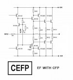
The first circuit is simply Musical Fidelity's A1 power amplifier redrawn, without component values.
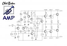
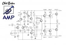
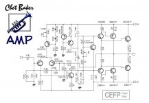
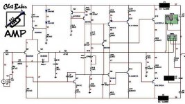
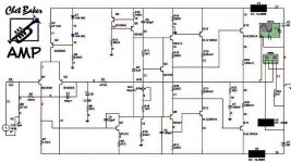
The "Chet Baker" Amp is a Rotel clone with a slightly different output stage - the graphics used for the schematic, style of compensation, plus the choice of transistors is identical to many Rotel service manuals.
The "Chet Baker" Amp is a Rotel clone with a slightly different output stage - the graphics used for the schematic, style of compensation, plus the choice of transistors is identical to many Rotel service manuals.
Thanks Symon
can you post a Bryston style output schematic example?
see the source of this idea:
http://www.esafono.it/ccc.pdf
can you post a Bryston style output schematic example?
see the source of this idea:
http://www.esafono.it/ccc.pdf
Attachments
there used to be a technical description on hte bryston web site, but can't find it right now.
take a look around the site.
Bryston Technical
this is the schematic of a Bryson amplifer
Bryston Schematic
You can also find discussion on Bryston amplifiers here on DIYAudio ..
take a look around the site.
Bryston Technical
this is the schematic of a Bryson amplifer
Bryston Schematic
You can also find discussion on Bryston amplifiers here on DIYAudio ..

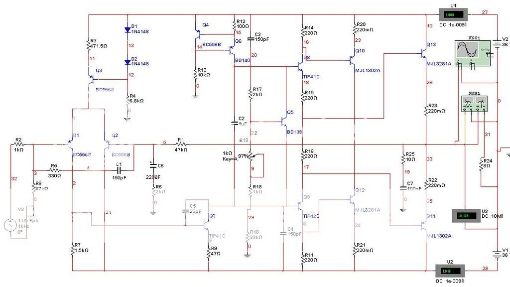
Beto said:In the original project could not a good result
modified some parts in the scheme to operate the simulator see the components changed:
R103 and R113 = 47k
R115 connecting a capacitor of 220uf to the ground.
R127 = 2k
Vr103 = 1k
R125 = 1k
q107 put capacitor 22pf of B / C.


Beto said:
Beto, your schematic looks off. Look at Q13's base. Shouldn't this be connected at Q8's emitter?
- keantoken
- Status
- This old topic is closed. If you want to reopen this topic, contact a moderator using the "Report Post" button.
- Home
- Amplifiers
- Solid State
- italian style