I have been simulating this circuit for a short while.
I think you may be interested in these models for the output devices that have been hand-made by andy_c. They are very accurate and will be more like real life.
http://andycpublic.50webs.com/spice_models_1.htm
Download link is at the bottom right corner.
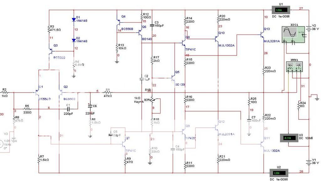
I played with the circuit in the simulator and this happened. Distortion is lowered considerably if we give Q7 a little gain.
THD @120W, 1KHz 8ohms=.009%
THD @120W, 20KHz 8ohm=.011%
This circuit seems to show potential.
There is more I can do for this circuit but I don't know if that is the purpose of this thread. Is it your aim to improve this amplifier design?
- keantoken
I think you may be interested in these models for the output devices that have been hand-made by andy_c. They are very accurate and will be more like real life.
http://andycpublic.50webs.com/spice_models_1.htm
Download link is at the bottom right corner.
I played with the circuit in the simulator and this happened. Distortion is lowered considerably if we give Q7 a little gain.
THD @120W, 1KHz 8ohms=.009%
THD @120W, 20KHz 8ohm=.011%
This circuit seems to show potential.
There is more I can do for this circuit but I don't know if that is the purpose of this thread. Is it your aim to improve this amplifier design?
- keantoken
Attachments
Hey keantoken.
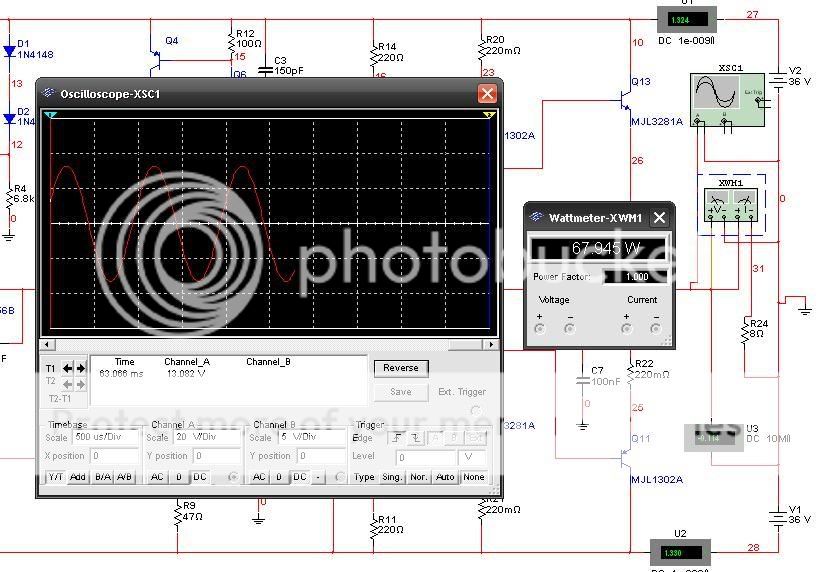
With +-36 Volt your nice figures are probably at 60 Watt RMS 8 Ohm.
Vrms = Vpeak/1.4142.... 60 Watt RMs in 8 Ohms = +-31 Vpeak.
It is one good amplifier. Some small goodies details.
Like R20, to reduce the open loop gain and improve linarity
and lower the feedback level a bit.
Regards")
With +-36 Volt your nice figures are probably at 60 Watt RMS 8 Ohm.
Vrms = Vpeak/1.4142.... 60 Watt RMs in 8 Ohms = +-31 Vpeak.
It is one good amplifier. Some small goodies details.
Like R20, to reduce the open loop gain and improve linarity
and lower the feedback level a bit.
Regards
Hi Lineup
The amp as shown is a rotel model 850 from 1990 or there about with improved output, like that used by bryston. Your comment about R20 is strange, Rotel changed this concept and the compensation to something different in later models to improve the sound. The resistor dissapears. There is nothing to be gained by reducing open loop gain, just more audio myths.
The amp as shown is a rotel model 850 from 1990 or there about with improved output, like that used by bryston. Your comment about R20 is strange, Rotel changed this concept and the compensation to something different in later models to improve the sound. The resistor dissapears. There is nothing to be gained by reducing open loop gain, just more audio myths.
Yes, I know
We have discussed this before.
Most logic is the opinion that maximal gain = maximal feedback correction
gives best result.
But here there is another opinon, too.
That too high feedback level is not only a good thing.
Eventhough it is not easy to explain why ...
We have discussed this before.
Most logic is the opinion that maximal gain = maximal feedback correction
gives best result.
But here there is another opinon, too.
That too high feedback level is not only a good thing.
Eventhough it is not easy to explain why ...
Lineup I know the arguments, and have played a lot with type of thing, I dont lower the gain by resistor to ground or rail, but in the vas it self, i find no benefit or harm done with the sound, to be honest didnt change the sound at all except when driving the amp real loud, with the smaller gain the distortion became hearable. I see rotel have gone back to using it in there more recent offerings. 
Hi Beto.
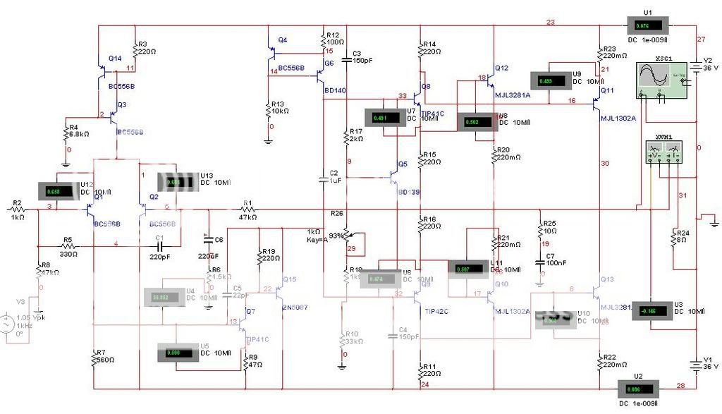
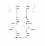
Your simulation probably would have looked like mine if you have used all same transistors I did. In my opinion you should get rid of the TIP4x devices, as these are made for power supplies and such. I don't think they are meant for Hi-Fi audio. I have made some more modifications and the circuit simulates quite well now. Look at the bottom of this post for THD figures and schematic.
I have not tested this sonically, but here is some experience from simulations:
1: If you use, say, 2N2222 transistor for the LTP, you will get krappy HF distortion even though you have a lot of OLG. Why? Because of Cob. The 2N2222 has Cob of 22pF! This is as high as the usual miller cap, and it increases distortion at high frequencies. It is best to use Low-Cob LTP transistors.
2: Using low-Cob transistors generally in an amplifier (except sometimes for the output stage), you don't get harmonics at 20KHz that trail on to the horizon. Instead, you will have the same harmonics you get at 1KHz, but a little more.
Not Ft, Cob. Since Cob provides a HF short, it causes distortion to be distorted, causing said harmonics. The BC857B wouldn't be my favorite device to use in an LTP, because if we switch over to an NPN LTP we can use the 2N5089 which has a gain of 1.4K but a Cje of just 5pF! The important thing is a good Cje to Hfe ratio when choosing LTP devices. EDIT: Wait, unless we split the rails we'll have to use MPSA18s here, which have a worse
3: The rest of the amplifier should be linear. If the output stage is not linear, then the amplifier will be working against itself. In this case, the output stage's distortion will only be divided by the OLG. It is like dividing a number by 10. You will always get a non-zero number. You can keep dividing by 10 but the number will never be zero. If the LTP or VAS has high Cob, this distortion will also be circulated in the amplifier, providing harmonics that trail on and on to the mid-KHz.
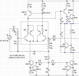
I would have posted a version sooner if I was sure that the aim of this thread was to improve upon the design.
Here is my modification to the circuit, leaving in the output stage which I think is the most unique part of the circuit.
THD at 60W, 8ohm, 1KHz=.0012%
THD at 60W, 80hm, 20KHz=.0036%
- keantoken
Your simulation probably would have looked like mine if you have used all same transistors I did. In my opinion you should get rid of the TIP4x devices, as these are made for power supplies and such. I don't think they are meant for Hi-Fi audio. I have made some more modifications and the circuit simulates quite well now. Look at the bottom of this post for THD figures and schematic.
lineup said:Yes, I know
We have discussed this before.
Most logic is the opinion that maximal gain = maximal feedback correction
gives best result.
But here there is another opinon, too.
That too high feedback level is not only a good thing.
Eventhough it is not easy to explain why ...
I have not tested this sonically, but here is some experience from simulations:
1: If you use, say, 2N2222 transistor for the LTP, you will get krappy HF distortion even though you have a lot of OLG. Why? Because of Cob. The 2N2222 has Cob of 22pF! This is as high as the usual miller cap, and it increases distortion at high frequencies. It is best to use Low-Cob LTP transistors.
2: Using low-Cob transistors generally in an amplifier (except sometimes for the output stage), you don't get harmonics at 20KHz that trail on to the horizon. Instead, you will have the same harmonics you get at 1KHz, but a little more.
Not Ft, Cob. Since Cob provides a HF short, it causes distortion to be distorted, causing said harmonics. The BC857B wouldn't be my favorite device to use in an LTP, because if we switch over to an NPN LTP we can use the 2N5089 which has a gain of 1.4K but a Cje of just 5pF! The important thing is a good Cje to Hfe ratio when choosing LTP devices. EDIT: Wait, unless we split the rails we'll have to use MPSA18s here, which have a worse
3: The rest of the amplifier should be linear. If the output stage is not linear, then the amplifier will be working against itself. In this case, the output stage's distortion will only be divided by the OLG. It is like dividing a number by 10. You will always get a non-zero number. You can keep dividing by 10 but the number will never be zero. If the LTP or VAS has high Cob, this distortion will also be circulated in the amplifier, providing harmonics that trail on and on to the mid-KHz.
I would have posted a version sooner if I was sure that the aim of this thread was to improve upon the design.
Here is my modification to the circuit, leaving in the output stage which I think is the most unique part of the circuit.
THD at 60W, 8ohm, 1KHz=.0012%
THD at 60W, 80hm, 20KHz=.0036%
- keantoken
Attachments
OK keantoken you are correct in their explanations. but we will await the opnião of Stee the original project was posted by him. what he thinks of the changes made in his project.
also think the project exceed my limitations in this area ehheehehehe still have much to learn from you great masters in the art of mounting amplifier.
thanks to all

also think the project exceed my limitations in this area ehheehehehe still have much to learn from you great masters in the art of mounting amplifier.
thanks to all
Its not always a good thing to change to NPN LTP, using PNP has its benifits, think in terms of rbb, besides what you gain with lower cob at the LTP you will lose with higher cob at the vas, theres a lot of compromises to be made. A tranny with very high gain and somewhat lowish cob is not that bad either, keep in mind that the higher gain device has high early voltage and this offsets the benefits of very low cob and lower gain.
Lineup was speaking in terms of lowering OLG by shorting the vas to ground or to a rail, the R20 in the spice schematic. A debate wich has lingered on these threads for ever. Is c6 and c7 really needed with this output arrangement ?
That cob is bad for amps is very true, even in outputstages this should be looked at, but not much you can do with standard output stage except use trannies with the lowest cob and highest early voltage.
a luky project
keantoken
I think you are a true professional designer
your product is an autentical masterpiece
probably come faster to be famous
my idea is build a class A module now
for that reason I have just buy 4x MJ15015 AND 4x MJ15016
(probably TO3 is best solution for big heating)
also Beto and the other friends are very nice
good team
Thank you Stee, and Beto.
I am not professional by any measure, since I have never had any kind of class on electronics. Everything I know I learned from DIYAudio (true story). So I would be right to say that my ideas are not original. An engineer might be able to do well in his field by studying other designs and copying the good ideas... But if you want something with better-than-normal specs, you have to think of new things. This creativity is what makes really good designers.
Thank you, everyone, for the small bits of advice I have received in this thread, as I could not do anything without your knowledge.
Before you posted this, I did not know about Rbb. I had basically assumed that all transistors were more or less equal in how many mV the base voltage goes up for how much base or collector current. Hmmm. How do you know Rbb for a given transistor? Can I know by looking at the SPICE models?
Yes, I thought of what I might be giving up for a VAS with a worse Cob-gain ratio.
About C6, C7 and R20, I don't know what effects they have on the circuit. I left them in because I had no reason to take them out. I was messing around in the simulator just now, and found that a small decrease in distortion resulted from the deletion of C6 and C7. I left R20 in because taking it out actually increased distortion some. But both times, the distortion change could have been considered "negligible".
It seems to me that using R20 to decrease OLG would only make the preceding stages work harder to produce the desired output. However on the simulator it actually decreases distortion b a very small amount. I am willing to bet the effect of R20 will be different depending on which circuit you are using. I also bet that R20 has an effect on the bias generator.
Also, look a this. Bryston style VAS! Also, R25 and C1. I am going to try the Bryston VAS on some of my circuits and see how well it works.
The Bryston seems to be a mix between a CFP and Darlington, giving high gain and good linearity.
THD at 60W, 8ohms, 1KHz is .00086%
THD at 60W, 8ohms, 20KHz is .00294%
- keantoken
I am not professional by any measure, since I have never had any kind of class on electronics. Everything I know I learned from DIYAudio (true story). So I would be right to say that my ideas are not original. An engineer might be able to do well in his field by studying other designs and copying the good ideas... But if you want something with better-than-normal specs, you have to think of new things. This creativity is what makes really good designers.
Thank you, everyone, for the small bits of advice I have received in this thread, as I could not do anything without your knowledge.
homemodder said:Its not always a good thing to change to NPN LTP, using PNP has its benifits, think in terms of rbb, besides what you gain with lower cob at the LTP you will lose with higher cob at the vas, theres a lot of compromises to be made. A tranny with very high gain and somewhat lowish cob is not that bad either, keep in mind that the higher gain device has high early voltage and this offsets the benefits of very low cob and lower gain.
Lineup was speaking in terms of lowering OLG by shorting the vas to ground or to a rail, the R20 in the spice schematic. A debate wich has lingered on these threads for ever. Is c6 and c7 really needed with this output arrangement ?
That cob is bad for amps is very true, even in outputstages this should be looked at, but not much you can do with standard output stage except use trannies with the lowest cob and highest early voltage.
Before you posted this, I did not know about Rbb. I had basically assumed that all transistors were more or less equal in how many mV the base voltage goes up for how much base or collector current. Hmmm. How do you know Rbb for a given transistor? Can I know by looking at the SPICE models?
Yes, I thought of what I might be giving up for a VAS with a worse Cob-gain ratio.
About C6, C7 and R20, I don't know what effects they have on the circuit. I left them in because I had no reason to take them out. I was messing around in the simulator just now, and found that a small decrease in distortion resulted from the deletion of C6 and C7. I left R20 in because taking it out actually increased distortion some. But both times, the distortion change could have been considered "negligible".
It seems to me that using R20 to decrease OLG would only make the preceding stages work harder to produce the desired output. However on the simulator it actually decreases distortion b a very small amount. I am willing to bet the effect of R20 will be different depending on which circuit you are using. I also bet that R20 has an effect on the bias generator.
Also, look a this. Bryston style VAS! Also, R25 and C1. I am going to try the Bryston VAS on some of my circuits and see how well it works.
The Bryston seems to be a mix between a CFP and Darlington, giving high gain and good linearity.
THD at 60W, 8ohms, 1KHz is .00086%
THD at 60W, 8ohms, 20KHz is .00294%
- keantoken
I think the CFP LTP is going overboard unless you're really stretching for a Hi-Fi design. In that case you might be more content to try and build and already existing design, like OStripper's Frugalamp or MikeB's Symasym.
I think you need to tell us how much effort you are willing to put into this.
Sorry, I forgot to attach my schematic in my earlier post. Although a bit off-topic, this is the improved version that I talked about in my earlier post.
- keantoken
I think you need to tell us how much effort you are willing to put into this.
Sorry, I forgot to attach my schematic in my earlier post. Although a bit off-topic, this is the improved version that I talked about in my earlier post.
- keantoken
Attachments
keantoken said:Thank you Stee, and Beto.
I am not professional by any measure, since I have never had any kind of class on electronics. Everything I know I learned from DIYAudio (true story). So I would be right to say that my ideas are not original. An engineer might be able to do well in his field by studying other designs and copying the good ideas... But if you want something with better-than-normal specs, you have to think of new things. This creativity is what makes really good designers.
Ok STEE and Keantoken thanks!
Keantoken, I hope one day also learn at least 50% of its attention on projects of amplifier. I am also not professional in the forum here and I'm trying to improve my knowledge in the area.
on the design of Stee was just trying to simulate the scheme to funcionase making some changes in its polarization for an adjustment of bias and offset for operation of the amplifier in accordance with the original project.
but glad that you came to give their verdict and to help the steel for the project decolase am very pleased to help you in any way since my knowledge is not as wide for the changes made by you.
Stee. cfp Ltp is good idea, its more linear than single transistor, easily incorperated into the schematic and will drop thd some more although it adds 2 more trannies to the design.
Btw, stay well away of those NTE transistors, they cheap and nasty. For a couple cents more get genuine japanese ones, or from onsemi or fairchild.
Btw, stay well away of those NTE transistors, they cheap and nasty. For a couple cents more get genuine japanese ones, or from onsemi or fairchild.
have true complementary power BJT
...get genuine japanese ones, or from onsemi or fairchild.
but do you know copules with the same hFE?
see another fine and easy italian design
http://digilander.libero.it/essentialaudio/unetto_circuit.htm
...get genuine japanese ones, or from onsemi or fairchild.
but do you know copules with the same hFE?
see another fine and easy italian design
http://digilander.libero.it/essentialaudio/unetto_circuit.htm
Attachments
- Status
- This old topic is closed. If you want to reopen this topic, contact a moderator using the "Report Post" button.
- Home
- Amplifiers
- Solid State
- italian style