Hello, all.
I have learned quit a lot about amplifier design, recently the Frugalamp thread has been a really nice resource.
I started out making a headamp, but I don't know exactly how well this will drive lower loads. It performs quite well with a 100 ohm load.
Distortion (simmed) at 1V pk-pk, 100 ohms, is >.001%, throughout the audio band.
Distortion at 100 ohms, 10V pk-pk at 1KHz is about .002% and at 20KHz it is about .006%.
My reason for creating this thread was so that I could learn what might make my amplifier impractical. Since I've never really built a working amplifier in real life, I figure this is a good idea.
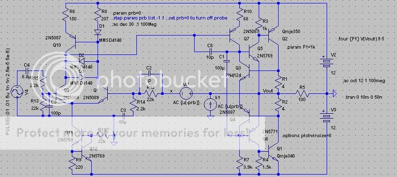
D1 and Q10 form a current mirror. Since the diode and the transistor aren't matched, R8 has been adjusted to compensate.
D2 and D3 improve clipping behavior.
Q3 and Q4 form the bias mechanism for the output pair, acting as a voltage amplifier. No doubt this has been done before, but my inspiration came from my experiments with the Rush cascode. These transistors should be mounted on to the output transistors, for thermal tracking.
I have a question:
1: If C2 goes higher than 4pF, the circuit oscillates. Is this a sign of instability, or does it indicate a healthy amplifier? Would having to use a cap this small have negative impacts on reliability (considering temperature coefficients and tolerance, etc.)?
Here is the schematic:
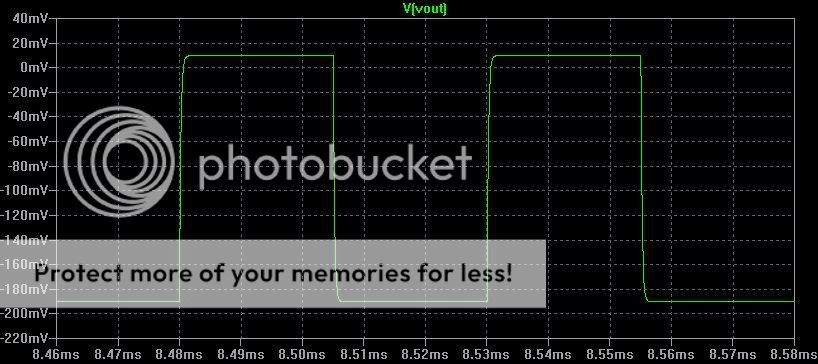
Here is the small-signal 20KHz squarewave response:
Thank you for your input,
- keantoken
I have learned quit a lot about amplifier design, recently the Frugalamp thread has been a really nice resource.
I started out making a headamp, but I don't know exactly how well this will drive lower loads. It performs quite well with a 100 ohm load.
Distortion (simmed) at 1V pk-pk, 100 ohms, is >.001%, throughout the audio band.
Distortion at 100 ohms, 10V pk-pk at 1KHz is about .002% and at 20KHz it is about .006%.
My reason for creating this thread was so that I could learn what might make my amplifier impractical. Since I've never really built a working amplifier in real life, I figure this is a good idea.
D1 and Q10 form a current mirror. Since the diode and the transistor aren't matched, R8 has been adjusted to compensate.
D2 and D3 improve clipping behavior.
Q3 and Q4 form the bias mechanism for the output pair, acting as a voltage amplifier. No doubt this has been done before, but my inspiration came from my experiments with the Rush cascode. These transistors should be mounted on to the output transistors, for thermal tracking.
I have a question:
1: If C2 goes higher than 4pF, the circuit oscillates. Is this a sign of instability, or does it indicate a healthy amplifier? Would having to use a cap this small have negative impacts on reliability (considering temperature coefficients and tolerance, etc.)?
Here is the schematic:
Here is the small-signal 20KHz squarewave response:
Thank you for your input,
- keantoken
About the 1pF - 4pF cap.
In a real amplifier such small capacitances can easily be present in the PCB tracks and wire between components.
But if the amp is not 100% stable in simulations, this is a warning sign.
Can be that the output, without any base stopper resistors and in sziklai configuration, can cause instability.
+-12V and 150 mA Class A bias is a good value for 68 Ohms headphones. But do not increase the power/heat more if you will use MJE340/350.
The bootstrap 100uF is unusual.
Normally R7 would be divided into 2 resistors with the bootstrap cap connect from the output to between resistors.
Hi Lineup.
I didn't want to put in base stoppers, so I put in R17 and R18. This brought the distortion down, and also increased stability.
I put the bootstrap cap as you described, and this brought the distortion down further!
Max THD at 1.5W, 20KHz is .0017%.
THD at 1KHz, 1.5W is .0004%
Thank you, Lineup.
- keantoken
The bootstrap 100uF is unusual.
Normally R7 would be divided into 2 resistors with the bootstrap cap connect from the output to between resistors.
I didn't want to put in base stoppers, so I put in R17 and R18. This brought the distortion down, and also increased stability.
I put the bootstrap cap as you described, and this brought the distortion down further!
Max THD at 1.5W, 20KHz is .0017%.
THD at 1KHz, 1.5W is .0004%
Thank you, Lineup.
- keantoken
I wouldn't call C1 in your first schematic a bootstrap but rather a bypass. The reason it lowers distortion so much is that the VAS is feeding into the high impendance collector of Q3 and the signal doesn't transfer very well to the collector of Q4 that feeds the lower output pair. This makes the output level from the upper and lower output pairs uneven. Bypassing Q3 and Q4 evens it up.
jerluwoo said:I wouldn't call C1 in your first schematic a bootstrap but rather a bypass. The reason it lowers distortion so much is that the VAS is feeding into the high impendance collector of Q3 and the signal doesn't transfer very well to the collector of Q4 that feeds the lower output pair. This makes the output level from the upper and lower output pairs uneven. Bypassing Q3 and Q4 evens it up.
Thanks Jerlu. I knew this though which is why C1 was there in the first place. After the addition of C7, anything higher than 100nF for C1 actually increased distortion.
C7 works by adding OLG to further decrease the impedance between the bases of Q5 and Q6.
- keantoken
Re: New info
Oop.
I think that's .0001 ohms, actually.
Anyways, a new development if anyone's interested.
I like this method better than the bootstrap, since you don't have parasitics piling up asymmetrically.
As I theorized, this method would be more stable than the bootstrap. It seems I was right, as the circuit is no longer so sensitive to the value of C2 and is even stable without it at 40KHz, max output.
Bias current through Q3 and Q6 will wander with temperature, but this should have no direct or significant affect on performance.
This might increase PSRR, but I don't think very much since supply fluctuations will only affect quiescent current.
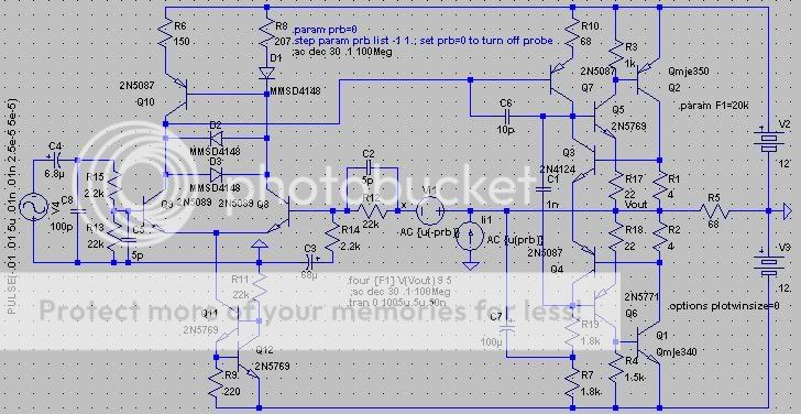
Schematic is attached.
I will have enough parts to build this sometime next week hopefully, so if it works I will post here.
- keantoken
keantoken said:Output impedance is .1mV.
- keantoken
Oop.
I think that's .0001 ohms, actually.
Anyways, a new development if anyone's interested.
I like this method better than the bootstrap, since you don't have parasitics piling up asymmetrically.
As I theorized, this method would be more stable than the bootstrap. It seems I was right, as the circuit is no longer so sensitive to the value of C2 and is even stable without it at 40KHz, max output.
Bias current through Q3 and Q6 will wander with temperature, but this should have no direct or significant affect on performance.
This might increase PSRR, but I don't think very much since supply fluctuations will only affect quiescent current.
Schematic is attached.
I will have enough parts to build this sometime next week hopefully, so if it works I will post here.
- keantoken
Attachments
They control the bias for the MJE340/350 outputs.
They limit the voltage across the R1 and R2 to about 1.3V but since the emitters aren't connected to ground it allows the current to change between R1 and R2. Perfect for class A, but you don't want to try AB with this.
They can be mounted on the MJe's, and so when they get hot the bias current will decrease.
I got the inspiration from the Rush cascode, which I have realized is used in more places than obscure amplifiers. Of course I'm not claiming that this idea is original, nothing is new under the sun.
- keantoken
This last change I do not like.
Will give bad PSRR, power supply rejection.
Because via: R10 - Q7 - R22 - Q13 - R7
the supply rails are in contact with eachother.
Any variation at power supply lines will change voltage across and current in R19/R22
and in the amplifier stage.
---------
In a good PSRR amplifier there should always be at least one
Transistor Collector between postive and negative supply node.
This is the case for example in the input constant current source.
Where this 'isolating' element is the Collector of Q11.
- Status
- This old topic is closed. If you want to reopen this topic, contact a moderator using the "Report Post" button.
- Home
- Amplifiers
- Solid State
- Discrete Class A amplifier for discussion.