Guys,
I need some help to develop this type of PSU.
The idea is to isolate the noise from transformer and rectifier.
The 50Hz hum noise could be removed with a super shunt or linear PSU inserted after the C2.
Could be this an first step for a battery like PSU?
Mihai
I need some help to develop this type of PSU.
The idea is to isolate the noise from transformer and rectifier.
The 50Hz hum noise could be removed with a super shunt or linear PSU inserted after the C2.
Could be this an first step for a battery like PSU?
Mihai
Attachments
Ecdesigns posted detailed schematics and a description of his 'never connected' circuit here. Never Connected?
Regards,
Dan
Regards,
Dan
roender said:What do you think?
It will probably depend on the power transformer inductance too. You've come up with a very simple circuit, not many excuses not to build it.
dantwomey said:Ecdesigns posted detailed schematics and a description of his 'never connected' circuit here.
Thanks for that. Will definitely check it out.
Something is wrong. Even in the other thread, there will be ripple because you are trying to charge the output cap from the input cap as well as draw current through a load, so you need to transfer twice the current.
There is another problem the output cap will only charge until the voltage on both caps are the same, which is lower than the start-up therefore there would still be ripple at 50 Hz.
Increase the load to something more than 1 k and you will be less happy with the results.
There is a final problem as I see it, as the voltage rises on the output cap and falls on the input cap the FET will turn of. Thus one would need a charge pump to ensure that the gate voltage remains high.
Nico Ras said:Something is wrong. Even in the other thread, there will be ripple because you are trying to charge the output cap from the input cap as well as draw current through a load, so you need to transfer twice the current.
There is another problem the output cap will only charge until the voltage on both caps are the same, which is lower than the start-up therefore there would still be ripple at 50 Hz.
Increase the load to something more than 1 k and you will be less happy with the results.
There is a final problem as I see it, as the voltage rises on the output cap and falls on the input cap the FET will turn of. Thus one would need a charge pump to ensure that the gate voltage remains high.
Hi Nico,
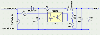
The main problem addressed by this type of regulator is not the 50Hz hum noise (which can be simply removed by any good regulator, with good PSRR) but the high frequency main noise.
The ratio between rising load and falling unload current in the output PI filter is far greater than 1.
In the last schematic there is no FET
")
Hi Roender,
It looks like the transistor is conducting while current is flowing through the rectifier, which is a direct path for mains borne noise.
In the ecdesigns circuit the mosfet only conducts below the input voltage when the rectifier conducts, so assuming the rectifier and mosfet have low capacitance there is no significant path for the noise.
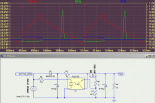
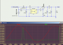
First thing to do is add a 100khz 1 volt signal to your input, then add a small inductor in series with the large capacitors because we know they won't filter HF in the real world.
Then check to see if the HF signal appears at the output.
It looks like the transistor is conducting while current is flowing through the rectifier, which is a direct path for mains borne noise.
In the ecdesigns circuit the mosfet only conducts below the input voltage when the rectifier conducts, so assuming the rectifier and mosfet have low capacitance there is no significant path for the noise.
First thing to do is add a 100khz 1 volt signal to your input, then add a small inductor in series with the large capacitors because we know they won't filter HF in the real world.
Then check to see if the HF signal appears at the output.
Symon said:Hi Roender,
It looks like the transistor is conducting while current is flowing through the rectifier, which is a direct path for mains borne noise.
You are correct. Instead of C1, a 100k resistor solve the problem
If this is for a pre/line amp would it not be better using a battery instead and charge it during the negative half cycle like you are doing here, thus replacing the output cap with a battery.
Following the battery is a small series regulator so that the charge ripple is rejected.
We make something very similar in an "all" voltage battery charger using the cap to transfer energy.
This method of charging expands the battery life since it is never allowed to run low.
Kind regards
Nico
Following the battery is a small series regulator so that the charge ripple is rejected.
We make something very similar in an "all" voltage battery charger using the cap to transfer energy.
This method of charging expands the battery life since it is never allowed to run low.
Kind regards
Nico
The circuit as shown is completely useless, not only due to the increased ripple and the noise produced by the own circuit, but because ground stays continuously connected and capacitively coupled to mains line, so it does nothing against common-mode noise.
You are trying to solve a problem that you don't understand at all. Differential mode noise from mains is completely filtered by transformer leakage inductance and smoothing capacitors. "Diode noise" are just two small spikes per mains cycle that are easily suppressed with proper RC networks.
It's common-mode noise what needs some filtering, and this is much easily achieved with common-mode chokes which do an excellent job with high frequencies and RF. Low frequencies are usually not a concern as long as the parasitic input-output capacitance of the mains transformer is low enough.
Hi Eva,
so how would you solve this riddle of having the power supply completely free from mains bourne intrusion. and of course noiseless.
I think we have all been down the path you are explaining for more than 40 years, it is time to look for something different, better, a new challenge.
so how would you solve this riddle of having the power supply completely free from mains bourne intrusion. and of course noiseless.
I think we have all been down the path you are explaining for more than 40 years, it is time to look for something different, better, a new challenge.
A true "floating capacitor" approach requires four bidirectional switches with very low capacitance and geltle voltage and current ratings, otherwise it can't be better than doing it the straight way. Soft switching is required too, so system efficiency won't be high.
In the end, the classic EMI filter schemes that have been used to make other noisy or sensitive equipment work properly for decades are the way to go, together with proper EMI considerations when laying out the interconnects and the grounds. But this is a complex electronics field that most audio designers don't feel like learning.
Creating myths may be funnier than learning the science behind it, but it does not bring you anywhere.
I cannot see why bi directional switches need to be used, the current only flows in one direction.
Soft switching would mean big power dissipation as your are operating the devices in linear mode.
It would appear as if you are not the type to develop new technologies but to just continue using what has been used for generations, regarrdless of advances and developments.
R&D is about the creation of new technologies and products, that is what I believe that Roender is trying to achieve.
Designing EMI filters and the like, I am quite familiar with, but this is about thinking laterally, what experienced engineers learned to do.
Kind regards
Nico
Eva,
Another insightful down-to-earth comment.The circuit as shown is completely useless
- Status
- This old topic is closed. If you want to reopen this topic, contact a moderator using the "Report Post" button.
- Home
- Amplifiers
- Solid State
- My idea for Flying Cap or Never-Connected PSU