The preamp sitting my home setup consists of JFET/MOSFET building blocks utilizing no global feedback .Threads that describe the varios functional blocks that have been in and out of the preamp over the past few years include "Open Loop Follies, Part 1", "JFET SRPP RIAA Amp", and "All American" Phono Preamp. Thus far, I have been quite satisfied with the listenability of the various circuits I've tried. For a line amp, I pretty much always used some sort of MOSFET or JFET-based follower. There have been times, however, that I could have used a little gain in the line stage.
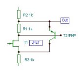
Line amps are funny customers. Trying to build a simple JFET circuit that will do just a little bit of boost and satisfy requirements for drain voltage centering for max signal swing is difficult. In the tube world, one could just grab a low-mu triode and use that. One possible solution would be to borrow the concept of SY's Heretical Line Amp and drive a follower of some sort with a step-up transformer, or park the transformer at the follower output. I may try that eventually. One other solution would be to give up and allow some feedback. The circuit shown below does just that. It is designed around the single positive voltage I use to supply my preamp chassis. Simulation results are encouraging. I had tried another line amp with gain a couple of years ago, but ripped it out after only a few hours because it just didn't sound right (the change in sonic characteristics was very obviously unpleasant). I may give this one a shot, pairing it up with a fast/quiet shunt regulator. As shown, the gain is ~10X - a little hot for my taste, but still usable. With some juggling of values and input stage bias currents, I could probably get lower gain with similar distortion characteristics. We'll see.
Line amps are funny customers. Trying to build a simple JFET circuit that will do just a little bit of boost and satisfy requirements for drain voltage centering for max signal swing is difficult. In the tube world, one could just grab a low-mu triode and use that. One possible solution would be to borrow the concept of SY's Heretical Line Amp and drive a follower of some sort with a step-up transformer, or park the transformer at the follower output. I may try that eventually. One other solution would be to give up and allow some feedback. The circuit shown below does just that. It is designed around the single positive voltage I use to supply my preamp chassis. Simulation results are encouraging. I had tried another line amp with gain a couple of years ago, but ripped it out after only a few hours because it just didn't sound right (the change in sonic characteristics was very obviously unpleasant). I may give this one a shot, pairing it up with a fast/quiet shunt regulator. As shown, the gain is ~10X - a little hot for my taste, but still usable. With some juggling of values and input stage bias currents, I could probably get lower gain with similar distortion characteristics. We'll see.
Attachments
I look forward to it, buffers are one thing, but when you need a touch of voltage gain this type of thing is the go, I have been toying around with various Borbely articles and have plenty of ideas, but have not put anything to use yet. I have a bag full of toshiba signal jfets, some lovoltechs and a quad of SS R550 and some (OK heaps of) mosfets so i'm fairly well armed
Actually the Toshibas (at least the J74 and K170) don't look as if they're really optimal for the job here - more suitable for something like a gain of 50. I want to keep the gain for this line amp down to 10 or less. So far, the circuit in my "Liniac Revisited" thread seems more suitable for high amplitude drive than anything in this vein I've simulated just yet. I'll keep trying, though
I was able to do a circuit somewhat similar to the one first posted that gives a THD at 0.5V input almost the same as the circuit in my "Liniac Revisited thread (a tad less than 0.005%, with an attractive harmonic spread). Things are still in simulation-land - I'll post more details when I have a circuit that I like better. I think this one is going to be in the "advanced" catagory, just like the Liniac.
I'm looking for a voltage gain of ~5. I already have loads of circuits for unity gain that work very well - that's easy. A gain of ~50 is relatively easy. A gain of 5-10 with proper voltage centering and acceptable distortion at line levels with a single supply of +30V is another matter. My "Liniac Revisited" circuit meets the criteria and is listenable. I'm looking for other alternatives hoping for a simpler circuit, but the constraints I pose make the job difficult. When I'm satisfied with the circuit variant I mentioned here, I'll post.
I'm looking for other alternatives hoping for a simpler circuit, but the constraints I pose make the job difficult.
Just go back to your first post:
One possible solution would be to borrow the concept of SY's Heretical Line Amp and drive a follower of some sort with a step-up transformer...
CineMag's CMMI-5C (1:5) and CMMI-10C (1:10) would be my recommendation.
se
I have the semiconductors - I don't have the transformers. If I try a transformer, I'll start a different thread, as it's a wholly different concept. Right now, I'm working with a box that has an RIAA amp (one of several different flavors - I've been looking at various concepts for 4-5 years), a capacitively coupled pot/attenuator (right now, I'm using a black Noble 50k "block" pot, maybe a switched resistor network later on), and the line amp. I tried using the pot straight without coupling, but the DC offset from my better CD player turns it into a hissing nest of snakes.
The pot/attenuator would be difficult to use with the transformer the way that SY has it, so for right now, I'll stick with a semiconductor solution that doesn't mind having 50k in front of it. I'm actually reasonably happy with the line amp I have now, it's just that the initial take of this circuit looked promising, except for the ability to handle high level signals with low distortion (it's also nice to have two solutions that work rather than just one). The simulation I made this afternoon actually matches my current "Liniac" solution pretty well in performance, but it uses too many different semiconductor types - I'd like to pare down the number of line items. It also has a clunky sort of "cut to fit" look about it - I want to see If I can do better and make a design that's more aesthetically pleasing to me.
The pot/attenuator would be difficult to use with the transformer the way that SY has it, so for right now, I'll stick with a semiconductor solution that doesn't mind having 50k in front of it. I'm actually reasonably happy with the line amp I have now, it's just that the initial take of this circuit looked promising, except for the ability to handle high level signals with low distortion (it's also nice to have two solutions that work rather than just one). The simulation I made this afternoon actually matches my current "Liniac" solution pretty well in performance, but it uses too many different semiconductor types - I'd like to pare down the number of line items. It also has a clunky sort of "cut to fit" look about it - I want to see If I can do better and make a design that's more aesthetically pleasing to me.
Member
Joined 2009
Paid Member
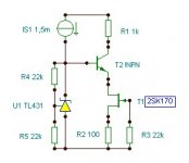
The 2SK170 could provide sufficient gain, otherwise this one is even better.
here's a method of implementing the Cascode bias that I like. I've not tried it myself, I found it on an old thread some time ago by a fellow countryman of yours that had a lot of good insight into some of these things.
Attachments
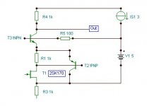
Attached is a variation on the first circuit I showed that works the way I want it to. The constraints are:
1) gain of 5-10X, preferably closer to 5
2) THD of 0.005% or less with ~ 1V out, with decent harmonic distribution. I design most of my amps for max output at 1V input.
3) Output voltage centered close to 1/2 Vcc for maximum symmetric output swing.
4) Vcc voltage of +30V
The lineamp uses 4 different types of semiconductors, but they are all ones I have, and none of them are terribly exotic or hard to find. Using the PN4391 at the input allows me to get decent bias current in the input stage with a relatively high Vgs. This helps to keep distortion down. I was surprised that the J176 worked so well in the second stage (I was using a cascoded 2SJ74 before), but there you go... The ZVN3306 (a Zetex part) is used so I can get high enough bias current in the output stage to drive both the feedback network and the load with low distortion. It is also in an E-line package that will handle the 200 mW quiescent dissipation well. I suspect that a PN4391 would work well in its place with a little biasing sleight of hand, but it would need a heat sink. A small metal plate and some Arctic Silver epoxy may be just the ticket for that option. I don't trust the TO-92 clip-on heat sinks, as their retention force is the pits, but a little Arctic Silver could possibly be all that is need to make that option viable.
In a real-world circuit, some small amount of compensation capacitance will be needed across feedback resistor R7. From my simulation work yesterday, it appears that somewhere in the region of 22-33pF will get the job done.
At any rate, I think I'll be building some variation on this circuit in the near future so I can compare it with my "Liniac Revisited" line amp.
Attachments
Last edited:
Joao, if you want to do a lineamp with low gain and no negative feedback, you're probably stuck with something like a low gain triode with current source loading (not that this is such a bad deal). It'll be inverting, which violates one of the criteria I didn't mention here, which is that I want the line stage to also be non-inverting.
WuYit - Snarky comments will get you nowhere with me. You are free to suggest an alternative (that is, a complete circuit) that more or less meets the criteria I set out. This doesn't mean setting out some squiggles with no values and expecting me to drop everything else I'm doing and work it out for you. You posted a couple of skeletons with no values and no analysis. Why don't you flesh one of those out, simulate it and compare?
WuYit - Snarky comments will get you nowhere with me. You are free to suggest an alternative (that is, a complete circuit) that more or less meets the criteria I set out. This doesn't mean setting out some squiggles with no values and expecting me to drop everything else I'm doing and work it out for you. You posted a couple of skeletons with no values and no analysis. Why don't you flesh one of those out, simulate it and compare?
Joao, if you want to do a lineamp with low gain and no negative feedback, you're probably stuck with something like a low gain triode with current source loading (not that this is such a bad deal). It'll be inverting, which violates one of the criteria I didn't mention here, which is that I want the line stage to also be non-inverting.
Tubes we are not talking about here. Of course you can do that but let's discuss a solid state line stage without NFB.
OK, you will have it non-inverting, then we should use a 2 stage design. Why not using 2 JFets or 2 MOSFets with current source loading of the source? Defining the amplification factor with the resistors should not be the problem and you can use 1 for the first stage like with a source follower.
- Status
- This old topic is closed. If you want to reopen this topic, contact a moderator using the "Report Post" button.
- Home
- Amplifiers
- Solid State
- JFET Lineamp with Gain