Nico Ras said:I am curious, how did you test the transistors. Were the light on only when you biased the gate?
I never start with the output transistors connected.
I just send the output back into the feedback loop in the LTP.
That way I know the driver circuit is working first.
ok, started all over from scratch, new transformer, new power supply, new power amp circuit...same thing, extremely loud hum then blows the fuses right away. I must have something wired wrong.
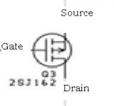
So is this correct when wiring in the 2sj162 (see attached picture) .....source is on top, gate on left and drain on the bottom?
I wish I could post a picture of my layout, but I can't...it matches the schematic from left to right is all I can say. Does this circuit actually work?
So is this correct when wiring in the 2sj162 (see attached picture) .....source is on top, gate on left and drain on the bottom?
I wish I could post a picture of my layout, but I can't...it matches the schematic from left to right is all I can say. Does this circuit actually work?
Attachments
all right, stayed up half the night and decided to build project 27b(100 watt mje3055/mje2955) from elliot sound/ westhouse..... works flawlessly. I am convinced that something in my 300 watt mosfet build is just plain wired wrong and I've spent to long on it to debug it anymore. Has anyone else here built the 300 watt mosfet? I am just curious if the mosfets I bought were really Hitachi and the pinouts were correct. I bought them from www.futurlec.com - really inexspensive. Per their site, the mosfets are Hitachi. Could someone post a picture of their 2sj162 and 2sk1058 so I can compare?

You purchased at $1.10 at the on-line store that you mention. This sounds a bit on the cheap side, they normally cost about $ 8 to $10 for genuine Hitachi.
If you have a magnifier, the name Hitachi is written inside the left hand top hole. The markings K1058 and J162 is laser etched onto the housing.
However, even if they were substandard one would assume that it should pass the 250 mA bias current without blowing.
You could try the amp with just one pair of output devices and repalce the fuses with 10 ohm 10 watt resistors or use Andrews light bulb technique to see if all is well before turning the real power on.
after more research, my transistors are fakes! I am assuming the pinouts are different.
http://images.google.com/imgres?img...bnw=119&prev=/images?q=2sj162&um=1&hl=en&sa=N
Any substitutes I could use in place of these?
http://images.google.com/imgres?img...bnw=119&prev=/images?q=2sj162&um=1&hl=en&sa=N
Any substitutes I could use in place of these?
http://digisec.co.za/ras/music/RAS 240 mosamp Rev02.zip
is the link to the project file and includes current PCB as built by several people.
The biggest problem I have had in the past is guys laying their own PCBs, but making mistakes when capturing the circuit diagram - I am not saying you did, but that is most common.
Keep in mind that this amp is not 300 watt as what is claimed on the web-site you got it from. I am not sure why this guy said so in the first place, maybe to attract people to his site.
Here is the link to the 340 watt 4 ohm version of this amp.
http://digisec.co.za/ras/music/300w MOSFET AMP.pdf
Kind regards
Nico
rtill said:after more research, my transistors are fakes! I am assuming the pinouts are different.
http://images.google.com/imgres?img...bnw=119&prev=/images?q=2sj162&um=1&hl=en&sa=N
Any substitutes I could use in place of these?
This circuit was designed for Lateral Mosfets, but with some component value changes it can be made to work with Hexfets. What have you got?
rtill said:I would have to see what the local electronic store has.... any examples I could use and if so, what values would be changed?
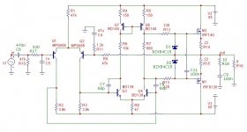
Okay here goes, probably not the highest-fi but now it uses more common MOSFETS IRF140 and IRF9130 and good for about 120 watt rms into 8 ohms using +-55V rails.
The BD139/140 are running at 350 mW and may need small heat sinks.
R7 could be a 1 K trim pot to set the quiescent current. With the resistor value shown it is about 350 mA.
Hope this satisfies your needs.
Kind regards
Nico
Attachments
rtill said:I would have to see what the local electronic store has.... any examples I could use and if so, what values would be changed?
I used IRFP240 and IRFP9240 pairs on my amp.
You can get them on ebay for a couple of pounds.
But you would need a proper bias circuit otherwise you will get either crossover disotrtion or the amp taking a lot of standing current.
Hi Rtill,
The kd998 and kb778 are not mosfets, beware, dont even try, the are high power audio bipolars second source manufactured by most probably KEC.
As for your problem with fakes please help yourself and others from falling into these traps with fakes. Return them to the shop, insist on a refund or their replacement with originals. If they get funny with you tell them you going to file a complaint and announce them all over the internet on consumer protection sites specially in the usa. Also that you will be informing Renaces of this situation, Renaces is original manufacturer. If they were selling these unknowingly they will refund immediatly, even if we are only talking of only a few dollars here youll be doing the electronics world a favour. Save all email correspondence with them especially their reply, if they dont act contact me and Ill give you a site to report this. Then send them a email to let them know that you have done this. We need to stamp this kind of b..lls...t out. At least they were charging less for them but its still decieving the consumer and misrepresentation, some charge the price of originals and give you fakes. If I were in usa I would personally give you a hand with this, I am sick and tired of being decieved too, I buy larger amounts and when someone does this to me I go after them.
Start a thread in electronics and parts and tell others of the situation so they dont fall into this trap too if you fail to have any response from them.
Nico Ras said:
Okay here goes, probably not the highest-fi but now it uses more common MOSFETS IRF140 and IRF9130 and good for about 120 watt rms into 8 ohms using +-55V rails.
The BD139/140 are running at 350 mW and may need small heat sinks.
R7 could be a 1 K trim pot to set the quiescent current. With the resistor value shown it is about 350 mA.
Hope this satisfies your needs.
Kind regards
Nico
nigelwright7557 said:
I used IRFP240 and IRFP9240 pairs on my amp.
You can get them on ebay for a couple of pounds.
But you would need a proper bias circuit otherwise you will get either crossover distortion or the amp taking a lot of standing current.
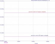
As you can see that bias can be adjusted quite accurately using a single pot of about 1k and 25 turns. I run mosfets at about 250 mA bias current and there is no crossover distortion.
The fixed resistor is set a little higher and you should never encounter cross-over distortion in this setup.
You can also see from the graphs that the system is stable under varying temperature conditions. It clearly shows that at higher temperature, the bias backs down.
This remains a very simple and robust little amp.
Nico
Attachments
- Status
- This old topic is closed. If you want to reopen this topic, contact a moderator using the "Report Post" button.
- Home
- Amplifiers
- Solid State
- transformer and transistor question