I didn't find a specific forum for maintainance/repair problems so I figured out I'd best post it where the pro's are likely to hang out ")
I've bought a HP 8903B analyzer from (indeed) ebay and it turns out it has the following problem:
I've tested it with its output connected to the input. When running distortion analysis it has good numbers (better than -90 dB) from 20 Hz up to 6 Khz, beyond that it increases to -60 dB at around 12 KHz. From 12 KHz upwards the distortion decreases to - 90 dB at 50 KHz. Strange!
At 1 KHz the unit reaches acceptable -95 dB distortion.
I'm using about 1 m. (3 ft.) of RG59 coaxial cable with BNC connectors (tried different cables as well). Although its 75 ohm and i've set the unit to 50 ohms that shouldn't be the problem at these frequencies.
I've monitored the residual on the scope with the following result:
@ 1 KHz --> Looks like simple noise to me, no more, no less.
@ 12 KHz --> Clear and stable 2nd harmonic at relatively high level!
I've tried adjusting the Notch filter tune and balance offset without any (positive) result, had to put them back to original position for best results.
So, the 1 million dollar question, who's got a clue?
(FYI, I was just getting my setup together so my advanced equipment doesn't go beyond a simple multimeter, a 50 MHz Phillips scope, two low-q signal generators and a few power supplies.)
HP8903B and problems
The manuals are on Agilent's web site. They have the two service manuals and the operation/calibration manuals. Try the following:
http://www.home.agilent.com/agilent/product.jspx?cc=US&lc=eng&nid=-35197.536881789&pageMode=PL
Cheers.
The manuals are on Agilent's web site. They have the two service manuals and the operation/calibration manuals. Try the following:
http://www.home.agilent.com/agilent/product.jspx?cc=US&lc=eng&nid=-35197.536881789&pageMode=PL
Cheers.
Not a clue, but be sure you don't have any other equipment near the unit during the test, particularly anything with a switching power supply or CRT. Definitely download the service manual from Agilent. The 8903, though it pretends to be a digital instrument, is mostly analog. Go through it in an orderly fashion, and don't desolder anything until you can prove that it's bad via measurements and logic.
Hi HighTower,
Welcome to the world of Eeekbay.
The first place to examine after you have the manual(s) is the power supply. Never overlook that. Then look for evidence of previous work done. Your eyes and brain are great service tools.
Nice score BTW. I use the 339A and I have a 334A that I'll rebuild and use (it goes higher in frequency).
Your oscilloscope should be more than good enough for your work. Just make sure you have good probes. If you have the automatic sensing X10 probe / 'scope combination, you will be in good shape. If you have X1 / X10 probes, glue one set (pair) into the X10 position. Most of your work will be done with this setting. The X1 setting tends to load circuits down capacitively, which can make them unstable. Also, your 'scope may only be good for +/- 5 V peak input. You don't want to blow it up.
-Chris
Thanks for the tips so far and the link to the service manual, didn't know it was online! Indeed this is the risk of ebay (eekbay) but since I can't afford a new unit this seemed the best option.
I've done some testing with the external low-q signal generators and I'm getting slightly better results at 12 KHz than with the external signal generator (stable distortion of - 60 to -70 dB over the entire freq. range). More important is the absence of the clear 2nd order harmonic at 12 KHz so I guess for now the eye is on the oscillator (which in itself doesn't exlude the power supply).
As for external sources of distortion I'll be sure to check, but besides the Scope it's mostly low-tech, no CRT's and as far as I know no SMPS powered equipment.
Something else I noticed when performing the distortion test:
When I increase frequency from 1 KHz to 12 KHz the clear 2nd harmonic is NOT present. If I then increase again to 13 KHz it suddenly is. Now, when I decrease frequency from 13 to 12 KHz the 2nd harmonic is ALSO present!!
I'll dive into the service manual after x-mass (not allowed to do so at the moment ) but I'm afraid I'm overlooking something simple and start searching at component level to soon.
Anyway, Merry Christmass!!
I've done some testing with the external low-q signal generators and I'm getting slightly better results at 12 KHz than with the external signal generator (stable distortion of - 60 to -70 dB over the entire freq. range). More important is the absence of the clear 2nd order harmonic at 12 KHz so I guess for now the eye is on the oscillator (which in itself doesn't exlude the power supply).
As for external sources of distortion I'll be sure to check, but besides the Scope it's mostly low-tech, no CRT's and as far as I know no SMPS powered equipment.
Something else I noticed when performing the distortion test:
When I increase frequency from 1 KHz to 12 KHz the clear 2nd harmonic is NOT present. If I then increase again to 13 KHz it suddenly is. Now, when I decrease frequency from 13 to 12 KHz the 2nd harmonic is ALSO present!!
I'll dive into the service manual after x-mass (not allowed to do so at the moment
) but I'm afraid I'm overlooking something simple and start searching at component level to soon. Anyway, Merry Christmass!!
Hi Conrad,
Hi HighTower,
You will find most signal circuitry in closed boxes, this includes the relays in the attenuator. If these are the ones I'm thinking of, they merely clip onto the PCB and press down on gold flashed pads. Clean with 99.9 % isopropyl alcohol. Drug stores can order this in for you if they don't carry it normally. It is not terribly expensive. I have never attempted to clean the contacts in one of these, but I may have to attempt this in the future.
-Chris
Yes, that sounds reasonable. I have had trouble with relays in all equipment of that vintage.The 8903 does a lot of internal range switching using relays.
Hi HighTower,
You will find most signal circuitry in closed boxes, this includes the relays in the attenuator. If these are the ones I'm thinking of, they merely clip onto the PCB and press down on gold flashed pads. Clean with 99.9 % isopropyl alcohol. Drug stores can order this in for you if they don't carry it normally. It is not terribly expensive. I have never attempted to clean the contacts in one of these, but I may have to attempt this in the future.
-Chris
Not a clue, but be sure you don't have any other equipment near the unit during the test, particularly anything with a switching power supply or CRT. Definitely download the service manual from Agilent. The 8903, though it pretends to be a digital instrument, is mostly analog. Go through it in an orderly fashion, and don't desolder anything until you can prove that it's bad via measurements and logic.
I got caught out with a sig gen on top of a scope interfering with the scope.
I also got caught out with a CFL lamp just above my work area. It had an oscillator inside it interfering with my work.
Step 1: Get the service manual.
Step 2: Verify that the supply voltages are within their specified limits both for DC voltage and ripple voltage.
Then, as others have pointed out, eliminate all interference sources (CFL, LED lights, WiFi routers, cell phones, etc.) and measure again. If still broken, follow the service manual.
The old HP service manuals are really good reads, actually! If you're going to use the instrument, I definitely recommend getting the manual. Artek Media and Manuals Plus are your friends there.
Tom
Thanks for your replies Nigelwright7557 and Tomchr, I will read the service manual, maybe I could some clues there.
Readings were taken with just the 8903B running a loopback, no other devices were ON or even pluged to the mains. I’m afraid the instrument has something wrong on the meter side.
Trying to put a sinewave from an external oscillator results in the same higher readings in the 12-14Khz region.
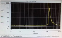
This pic shows the behavior of the loopback THD plot. No senstitive emiting devices around the 8903B.
Thanks for your help
Readings were taken with just the 8903B running a loopback, no other devices were ON or even pluged to the mains. I’m afraid the instrument has something wrong on the meter side.
Trying to put a sinewave from an external oscillator results in the same higher readings in the 12-14Khz region.
An externally hosted image should be here but it was not working when we last tested it.
This pic shows the behavior of the loopback THD plot. No senstitive emiting devices around the 8903B.
Thanks for your help
I got the exact same 2nd harmonic issue with my HP8903A, the harmonic appears when set oscillator to floating output, and output level to lower than 0.59V. When set output level above that, the relay clicks and harmonic goes away. the harmonic is not from oscillator board and first half of attenuation board, I had tapped the AMP3 TP on A6 board, the signal is clean, however harmonic shows up on A6 TP2 and TP3. Any suggestion where to look?
Hello everybody.
This it's my first post in this forum that I frequently read.
Just in this week I bought an HP 8903A in eBay in very good shape but no completely tested by the seller.
I have tested the power supply and it`s ok. No excesive ripple.
Also I tested the THD source generator directly output to input and I found exactly the same pattern that albertd200 found: Between 12.5 KHz and 20KHz the THD are excesive, more of 0.1% (2nd armonic).I used the Peter Millet`s software and a NI PCI card.
After an investigation over the source-oscillator card this is ok.
But in the P/O A3 Notch filter card I have found two electrolytic capacitor open, C2 and C3 in the +15/-15 input filter rail. Once the electrolytic ones are replaced everything is fine and the THD for the 20 Hz to 20 KHz it`s between 0.0016% and 0.0027%.
I hope that this little help will be useful for the HP 8903A's owners with troubles.
Saludos
by the way, thanks Dedalo for the hint. I had the same problem, high THD above 12.1K, replaced C2 and C3 that were essentially not functioning and it cleared it all up.
Thanks again
Jerry
There are three traces. Two overlap and you can see the problem. The light orange trace is after changing the caps on A3, C2 and C3. The spike in the low frequencies is somehow related to my scanning program not allowing for settling.
Thanks again
Jerry
There are three traces. Two overlap and you can see the problem. The light orange trace is after changing the caps on A3, C2 and C3. The spike in the low frequencies is somehow related to my scanning program not allowing for settling.
Attachments
Last edited:
- Status
- This old topic is closed. If you want to reopen this topic, contact a moderator using the "Report Post" button.
- Home
- Design & Build
- Equipment & Tools
- Problem with HP 8903B distortion analyzer