Those are all headed my way. ")
In the process of purchasing some little caps to finish up a project, I got all fascinated over the possibility of building a transistor amp.
I was thinking that those new parts could make some classic sounds like NEC's original B618, D588 with A1567, A794 as seen in the Technics, circa 1975, opening day product line.
Problem: The modern equivalent for half of that was missing, so I had to go with the new manufacturer's suggested complimentary part. The two smaller NTE made no sense to me (television parts?), so I got a backup plan from ONsemi (audio parts).
For pre, I also got several of every transistor listed as seemly in the Decibel Dungeon discrete buffer project as well as some not-so-close equivalents to C828.
Unfortunately, that was as far as my plan got me. Oops!
I'm in need of a PCB or a photograph of a seemly way to wire the power amp on perfboard.
Is there any chance that there's a newbie help document with remarkably understandable documentation? Yes, a resistor goes there and here and everywhere else, and yes I can assemble a kit. Boring! I want to know, and neither a slew of indecipherable documents nor a kit will do it. Help?
In the process of purchasing some little caps to finish up a project, I got all fascinated over the possibility of building a transistor amp.
I was thinking that those new parts could make some classic sounds like NEC's original B618, D588 with A1567, A794 as seen in the Technics, circa 1975, opening day product line.
Problem: The modern equivalent for half of that was missing, so I had to go with the new manufacturer's suggested complimentary part. The two smaller NTE made no sense to me (television parts?), so I got a backup plan from ONsemi (audio parts).
For pre, I also got several of every transistor listed as seemly in the Decibel Dungeon discrete buffer project as well as some not-so-close equivalents to C828.
Unfortunately, that was as far as my plan got me.
Oops! I'm in need of a PCB or a photograph of a seemly way to wire the power amp on perfboard.
Is there any chance that there's a newbie help document with remarkably understandable documentation? Yes, a resistor goes there and here and everywhere else, and yes I can assemble a kit. Boring! I want to know, and neither a slew of indecipherable documents nor a kit will do it. Help?
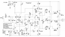
Looks like you already have the VAS and drivers (BD139/140) for a lower power (+- 45V) Self "blameless" design..
I don't know about those NTE parts, except they cost 10 times
as much as better Mouser.com parts (KSA1845/KSA 992).
With your BD's and 10$ in better parts (NJW 1302/0281)outputs..
$1.40 apiece ..,one could have a real good 60-80W discrete amp.
[Real simple amp above]
For simplicity, leave out Q3/4-R3/4.. replace with 1k resistors,
Q6/8/9/10 can be your BD139/40's.. just 1 pair NJW1302/0281
and a 30-0-30 tranny + rectifier/caps , your good to go..
OS
I don't know about those NTE parts, except they cost 10 times
as much as better Mouser.com parts (KSA1845/KSA 992).
With your BD's and 10$ in better parts (NJW 1302/0281)outputs..
$1.40 apiece ..,one could have a real good 60-80W discrete amp.
An externally hosted image should be here but it was not working when we last tested it.
[Real simple amp above]
For simplicity, leave out Q3/4-R3/4.. replace with 1k resistors,
Q6/8/9/10 can be your BD139/40's.. just 1 pair NJW1302/0281
and a 30-0-30 tranny + rectifier/caps , your good to go..
OS
Swapped for OnSemi parts
I would not wish to use NTE parts that are worse than Onsemi's parts. Since there was a backorder, I was able to change my order.
8 each of
bd140
bd139
4 each of
njw1302
njw3281
njw0281
njw0302
mje15032
mje15033
As you can see, I was a bit confused over which output transistors to purchase, so I got those possibilities covered. The order changes did not significantly increase the expense. Thanks guys!!!
One thought, is that I would like to drop the gain down to just enough to produce full power at the output without overloading the input--the minimum advisable gain. That should help avoid putting extraneous amplification on aberrations introduced by Onsemi and myself.
The photographs so kindly contributed show a seperate placement on the amplifier board for the 100uF caps. So, I'll need your recommend on some 100uF, 100v caps--whatever model you use for seemly, clear, results.
And, is there a way to purchase a PCB for this project?
Thanks again!
I'll be making a layout for this amp soon...(near the new year)
simple as possible..
22 K for r2/12 will bring the gain down for a smaller amp ,(40-50v)
rails. you might want to adjust r10 ,as this sets LTP (input differential) current . For a 45V PS ,270-300R will give you
1.8-2 Ma for each LTP.
Any will do.. panasonic's or nichelon ( I think I spelled that right)
This amp is so simple I built it on a plug in experimenters board.
first get the CCS working (Q5/LED) then build the whole amp
except for the outputs. Tack 2 47r resistors from emitters of Q9/10
(make sure you heatsink them!!)
to output for a small 10w amp to verify proper operation..
NO burnt OP devices . Then adjust r20 about half way
(500R)...all ready for your OPS (NJL0281/03020).
These amps have NO noise, almost no "turn on thump"
you will be surprised..(read any of Douglas self's books on
amplifier design for theory on amp ..google it.)
OS
simple as possible..
By DWB -One thought, is that I would like to drop the gain down to just enough to produce full power at the output without overloading the input--the minimum advisable gain. That should help avoid putting extraneous amplification on aberrations introduced by Onsemi and myself.
22 K for r2/12 will bring the gain down for a smaller amp ,(40-50v)
rails. you might want to adjust r10 ,as this sets LTP (input differential) current . For a 45V PS ,270-300R will give you
1.8-2 Ma for each LTP.
By DWB -100uF, 100v caps
Any will do.. panasonic's or nichelon ( I think I spelled that right)
This amp is so simple I built it on a plug in experimenters board.
first get the CCS working (Q5/LED) then build the whole amp
except for the outputs. Tack 2 47r resistors from emitters of Q9/10
(make sure you heatsink them!!)
to output for a small 10w amp to verify proper operation..
NO burnt OP devices
. Then adjust r20 about half way(500R)...all ready for your OPS (NJL0281/03020).
These amps have NO noise, almost no "turn on thump"
you will be surprised..(read any of Douglas self's books on
amplifier design for theory on amp ..google it.)
OS
MJL21193 said:Ah, welcome Dan, master of the chip amp realm, now set to reek havoc on the world of discrete design!!
OS has a nice amp here - a fine project for you to cut your teeth on.
Good luck and have fun.
Wonderful post!! Havoc indeed.
I laughed so much when I read the first part. Well, I did recently manage to turn the full range forum upside down, with a little help from Leslie Gore to provide the Sunshine, Lollipops, and Rainbows, and a garage with less roof, no doors. The thread was so interesting and turning criticism into constructiveness was fantastic.It took many years for me to learn how to make scalable speakers that I can get real music from, and a year to figure out op amps, so I don't expect to be able to do some near-magic with discrete design for quite some time.
Right now I'm looking for points of reference.
For instance, I'm having a bit of trouble comprehending the current mirror thing, I don't understand Q8 at all, and my handmade FM radios are great at tuning in anything except FM.
The discrete amplifier design that I really want to make is quite similar to the Frugalamp. I mean, its so close!! Right now, getting that close would be a very good thing.
By DWB -For instance, I'm having a bit of trouble comprehending the current mirror thing, I don't understand Q8 at all
Hi, Daniel.. The current mirror (Q3/4) is an optional component
that balances out the current used by the differential (Q1/2).
You can use them or not (only 2 - $.07c components). They
might reduce distortion from .05% to .005% at 1KHZ...
Q8/6 is the VAS (voltage amplification stage) , it is what
gives you that big 80v p-p wave at the output stage..
C14 (68pf cap) Is Cdom, it keeps you from building an oscillator
and it's value determines the high frequency characteristics of
the amp.
And finally Q7 and its associated components Bias the
drivers (Q9/10) which in turn bias the outputs, Q11/13..etc.
Q7 should be on the heatsink with the outputs to
feedback thermal compensation...
These are just a little harder than IC amps as component choices
are more demanding (resistor values in particular).. but
this circuit is very forgiving and with average care you
should have no issues...
OS
Hi! I like the current mirror circuit. My comment was that my understanding of it is a bit feeble at this time.
Its Q6, Q7, and Q8 that are currently escaping my comprehension.
I have no complaints about anything on the schematic. . . with only one exception. That exception is the LED. The lifespan of an LED could be a limiting factor and they do change in performance over time. This worries me. May I use a quality diode instead? And, if so, what sort? EDIT: Maybe MA150?
Thanks again!
By DWB- The lifespan of an LED could be a limiting factor and they do change in performance over time
In this circuit the led is run at 5ma.. most are rated at 20+,
so 5-7 years for a normal LED application (toys, Xmas lights)
but most likely 20 years at 5ma.
If you want to do 2 diodes instead of the led, change r10/330R
to 270R to keep the current to Q6 and the input stage
to an adequate level..
Really quite simple, Q6 (biased by the led)sets the current for all (Q7/8) Q8 is modulated by the signal from the input, givingIts Q6, Q7, and Q8 that are currently escaping my comprehension
a much larger voltage swing out the the power stages.
BTW , go into my WWW and all the simulations are there for
it.. in [electronics/projects/audio amp/frugalamp]
In [electronics/software] is LTswcad4.exe , a wonderful
freeware simulator.. It can help you tailor this circuit for any
power supply or power level..
OS
Wow that's a very cool web site.
Yes, I'll be trying out your simulator suggestion. Thank you!!
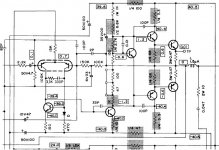
I'll bet you'd like to know why I had originally ordered the NTE parts that replace specific NEC part numbers? Well, here's the reason why (from Technics 1975-1977 opening day product line):
Yes, I'll be trying out your simulator suggestion. Thank you!!
I'll bet you'd like to know why I had originally ordered the NTE parts that replace specific NEC part numbers? Well, here's the reason why (from Technics 1975-1977 opening day product line):
Attachments
an LED (light emitting diode) is a quality diode.danielwritesbac said:..........with only one exception. That exception is the LED. The lifespan of an LED could be a limiting factor and they do change in performance over time. This worries me. May I use a quality diode instead? And, if so, what sort?
Many are lifetime specfied to >=50,000hrs.
AndrewT said:an LED (light emitting diode) is a quality diode.
Many are lifetime specfied to >=50,000hrs.
Panasonic MA150 lasts, in practice, more than 280,000hrs.
EDIT: The time that either will operate before going off-spec for electrical characteristics, is much shorter.
The time that either will operate before going off-spec for electrical characteristics, is much shorter
But by then , we will all have have class d or proton amps..
OS
ostripper said:But by then, we will all have have class d or proton amps..
OS
Well, in comparison, the LED is quite durable. My prosound friends keep telling me stories about class d amps, exacerbated comb filtering on arrays, mystery static, olive colored smoke, odd whistles, overheats, plasma fire, lost paychecks, crackle noises, and melted wiring are the usual complaints. So, maybe I shouldn't complain about an LED?
Hey, did you see my post (#13) with the excerpt from the old service manual? Do I spot a miller cap, a baxandall loop, and a T-network? I wonder why it has one less transistor? I'm so curious.
Hey, did you see my post (#13) with the excerpt from the old service manual? Do I spot a miller cap, a baxandall loop, and a T-network? I wonder why it has one less transistor? I'm so curious.
That is the "bootstrap" cap , it replaces Q6 in my amp.
I designed one (FA1B) with 2 -4K7 R resistors and a 100uf- 63V
NP cap fed back from output to replace Q6. This topology has
a natural gain rolloff over 200k and some argue that it also
has a better sound (tubelike).
OS
ostripper said:
That is the "bootstrap" cap , it replaces Q6 in my amp.
I designed one (FA1B) with 2 -4K7 R resistors and a 100uf- 63V
NP cap fed back from output to replace Q6. This topology has
a natural gain rolloff over 200k and some argue that it also
has a better sound (tubelike).
OS
Well, I really do want that.
- Status
- This old topic is closed. If you want to reopen this topic, contact a moderator using the "Report Post" button.
- Home
- Amplifiers
- Solid State
- First discrete amp, Need help with NTE 390, 391, 375, 398, and BD140, 139 project