Dadod ,as I said the cob of the power bjt+drivers are important for thd and sound also .If you don't have models for 2sc5200,SA1943 and 2SC5171,1930 I will share later .
And an important aspect is that human ear is making difference to the low thd at low power 1-3 watts .For 100 Watts the ear or brain is making the difference impossible to hear.
Also for listening at home 1-3 watts is often used .
And an important aspect is that human ear is making difference to the low thd at low power 1-3 watts .For 100 Watts the ear or brain is making the difference impossible to hear.
Also for listening at home 1-3 watts is often used .
Last edited:
Don't think if I ask some questions that I don't like your amp, I think it is very good and I like your "twisted" ideas about NFB.
I used some of it here http://www.diyaudio.com/forums/solid-state/186981-bootstrapsccs-t-tmc-15.html#post3197373 and later I designed this amp http://www.diyaudio.com/forums/solid-state/221901-little-gem.html.
dado
I used some of it here http://www.diyaudio.com/forums/solid-state/186981-bootstrapsccs-t-tmc-15.html#post3197373 and later I designed this amp http://www.diyaudio.com/forums/solid-state/221901-little-gem.html.
dado
Don't think if I ask some questions that I don't like your amp, I think it is very good and I like your "twisted" ideas about NFB.
I used some of it here http://www.diyaudio.com/forums/solid-state/186981-bootstrapsccs-t-tmc-15.html#post3197373 and later I designed this amp http://www.diyaudio.com/forums/solid-state/221901-little-gem.html.
dado
No Dadod ,I didn't say this .I just want to help to get the same results .Excuse if I am a little "hard" speaking .
I am happy that you have better results with my tweaks .I call this cascode miller compensation .
Personal I am a fan of the thd at 20khz ..
The results are more important in stability terms .
On some layout's this ideea is help a lot to get rid of some instability .Also the phase reserve is better .
And another advantage by using this kind of compensation is that the DC potentials on the cap are almost equal to 0 .May be you know that every cap has a internal noise directly dependent with the dc voltage applied .
Last edited:
Jay ,I don't remember to have a schematic with cascode ...
Always pay attention to the simulation ,idle currents and models .
Ups, only current mirror. I mixed up with Wahab's amp for Gaborbela.
Attachments
Here is my bjt models+transient ltspice sim .
Dadod ,my model of temperature compensation bjt was corupted .Is fixed now .
Jay ,I will post a version of no current mirror for you .I am also adept to simplier things .By removing the current mirror and the ef before vas we can put a miller cap of a half from what is now ,6pf .
What I don't like in that version is the dc offsets with the temperature though the olg at 20khz is almost the same with one with current mirror so we can achieve almost the same thd at 20khz .
Attachments
Last edited:
For Jay
For Jay :Joy_res :the no current mirror in attach .And I think is one of the vfb amp's with the lowest phase in OLG and also miller cap .
For both I am interested to design a load for the vas to be current non-dependent with temperature ,can be a resistor without bootsrap or a current mirror") .
.
What encyclopedia do you have on your pc !
Also I think that both versions can work with +/-10mV at output without the 22uF input cap
For Jay :Joy_res :the no current mirror in attach .And I think is one of the vfb amp's with the lowest phase in OLG and also miller cap .
For both I am interested to design a load for the vas to be current non-dependent with temperature ,can be a resistor without bootsrap or a current mirror
.What encyclopedia do you have on your pc !
Also I think that both versions can work with +/-10mV at output without the 22uF input cap
Attachments
Last edited:
Hi Catalin, thanks.
I would say that the FFT of your first circuit is equal with P3A, except that your circuit running much higher bias current, and one special characteristics of the P3A is the beautiful distortion profile.
I haven't check the AC analysis of your circuit, but P3A is wonderful there.
The second circuit is interestingly good, especially very good for low SPL listening. The THD for high SPL is very bad tho.
I think I will use both P3A and your circuit to benchmark my SSA-CFP.
Hi Catalin, thanks.
The second circuit is interestingly good, especially very good for low SPL listening. The THD for high SPL is very bad tho.
I think I will use both P3A and your circuit to benchmark my SSA-CFP.
I don't remeber my first circuit .Can you direct to the schematic ?
Why do you say that the thd is very bad for high spl ?
Last edited:
I don't remeber my first circuit .Can you direct to the schematic ?
60-80W Power Amplifier
ADD: Or may be you're asking the joy_sin.asc, the one with current mirror.
Why do you say that the thd is very bad for high spl ?
Sorry, I used to see amp behavior from the very first seconds the signal is applied. It is probably not valid to say so, but whatever, I like to see a homogenous FFT for input signal from 0.1 to 0.7 at short stop time:
Attachments
Last edited:
Yes Jay ,Thank you .The resistive load version is modded from the current mirror for your interest .I will continue for the moment with the current mirror version but if you are interested we can improve also the resistive one decreasing the emittor ltp if you are a "searcher for best thd" .But doing this the miller cap must be increased which I don't prefer .
As I said my interest is for the first 1-10watts ,enough in a 20-30 mp room .
More than this can't be detected related to thd . Also I prefer exactly the sound of the one with current mirror and small current feedback .
I see that the R21 resistor which is setting the current of the ltp is 560 ohms by my hurry .It should be 220ohms to have almost 3 mA in Ltp
Last edited:
purely dc coupled cfb version
Hello ,
I changed the vfb in a purely cfb dc direct coupled .No capacitors in the signal ..The node between R2 and R3 is virtual ground so there is no cap also in the feedback.
I will listen in the evening . 6mV dc output .If I like it, I will try to throw away the current mirror and the emitter follower to the vas .
The dc offset is also stable at different temperatures and also with/without short to gnd input .
Last edited:
Emitter follower
Probably unwise to lose the the emitter follower preceding the CFP.
More non-linear loading of the VAS will be the panalty of removing the follower.
Real life implementation of the circuit would probably be a challange, especially when it comes to the correct temperature tracking of the follower and the CFP combination.
Nice threat!
regards,
Piersma
Hello Piersma, I was not talking about the ef preceding vas. I was talking about the ef between ltp and vas.If I will remove the current mirror in a future I don t see a good reason to keep the ef .
Thank you!
Last edited:

R22=10k seems a bit high. Does your sim show a Vdrop ~7V?
That Vdrop will change slightly with signal and result in a significant variation in Vce for Q16
I have been using 1k0 to 2k0 here.
Some use 0r0 and then complain the transistor blows up.
Using 1k0 limits the worst case dissipation in Q16 to ~220mW when Vsupply = +-42Vdc.
That Vdrop will change slightly with signal and result in a significant variation in Vce for Q16
I have been using 1k0 to 2k0 here.
Some use 0r0 and then complain the transistor blows up.
Using 1k0 limits the worst case dissipation in Q16 to ~220mW when Vsupply = +-42Vdc.
Last edited:
R22=10k seems a bit high. Does your sim show a Vdrop ~7V?
That Vdrop will change slightly with signal and result in a significant variation in Vce for Q16
I have been using 1k0 to 2k0 here.
Some use 0r0 and then complain the transistor blows up.
Using 1k0 limits the worst case dissipation in Q16 to ~220mW when Vsupply = +-42Vdc.
Hello Andrew ,
There are 2 reasons for that value of R22 .
Q16 is a ef for the signal ,but :
Q16+R23 is creating a current source for the collector load of Q16 .So the current in load will be the same always and independent by the load value .So even if we increase the load the ef will do the same job .
One of reasons is that in transient mode the maximum current in Q16 and also Q6 (if we don't have R22) will be more than the maximum acceptable of the transistors beacuse the current is not limited in Q16.
In this case the ef will be distroyed .
But if we introduce R22 we introduce a current limit through Q16 of about = (V-) / R22 ~4mA .So the current limit is about 4mA but the current through ef will be decided by the 1kohm resistor from emitter of Q16 .Threfore the current is ~0.8mA .Now from the loadR22 point of view we have a constant current source (0.8mA) + current limitter (4mA) .
The key here is to calculate the resistor to have a voltage drop less than (rail voltage - ) - 3volts .Vce is varying from 30Volts only with maximum +/-0.3Volt so there are no issues .The constant current is helping a lot .
Now the second reason but for me is more important than the first one is that the AC transfer function is better with R greater .By doing this we move the dominant pole to a higher frequency which means that we can decrease the miller cap .This is one of the reasons why this amp is stable with 12pF and reach more than 100V/us SR .
Last edited:
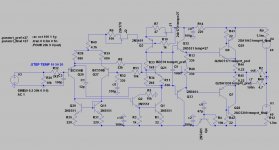
Temperature and supply independent .
A major flaw to these topologies is the psrr .
Psrr was bad to the negative rail so I improved with capacitance multiplier circuit .
Another major flaw of the audio amps is that the idle current varies with current from the vas which varies with temperature.
Now from -10 to +60 degrees Celsius the vas current varies only with 10uA .
I will listen the vfb and after that the cfb mod.
The thd figures are better than previous .At 20khz from 1Watt to 100W thd <0.003% by keeping the same SR >100V/us
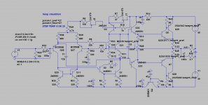
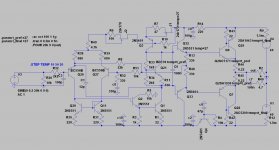
Joy version 5
@Jay: Hello Jay ,can you do the same simulation for all the power levels like before ?
Idle current should be 20-22mA through 0.22 ohms resistors.
Also the library is attached .
Thank you !
We can take also the negative feedback from the common point of the 330 ohms resistors if we want this ,thd will increase in this way from 0.002 to 0.02 % but the output will be a pure buffer . I want to build a pcb layout with this version v5 .
By this I will have a lot of options like a cfb amp,vfb amp and a output stage which is not in the feedback loop .
Also I want to have 2 pcb's separated ,one for the voltage gain and the other for the current gain(output stage) .
Attachments
Last edited:
Let's get low
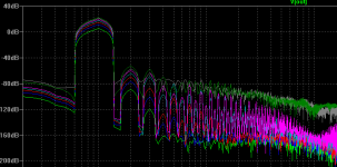
Getting better thd figures with 22 ohms resistor in drivers 5171,1930 .
And also the imd figures are very low .
The current through drivers is now 20 mA and thd at 20khz with 9 harmonics at 1 to 3 watts is 0.0005 % .No tmc or other kind .
The joy here is that the final stage is biased only with 10mA -12mA .
And the version without negative feedback (nofb) over the final stage has only 0.01% thd at 20khz .
Attachments
Last edited:
22r & 20mA gives an output Vbe of 440mV.
Is that correct? This seems far too low. I would expect 550mVbe to 600mVbe, giving a driver bias current range of approximately 25mA to 27mA
10mA to 12mA of output bias must be excluding the driver current.
The total current bias through the emitter resistor must be: driver bias + driver base current + output bias, i.e. approximately 35mA to 40mA.
Is that correct?
Last edited:
- Status
- This old topic is closed. If you want to reopen this topic, contact a moderator using the "Report Post" button.
- Home
- Amplifiers
- Solid State
- a wonderfull sziklai