Catalin,
can you tell me which feedback route dominates?
Is that the same as asking which controls the final gain?
and is that more or less important than the route that has less feedback.
I am thinking of a pair of nested feedback loops in a composite. I can't see it any other way.
In the composite, the outer loop controls the overall gain, but the inner loop limits the gain of one stage. That then has an effect on the feedback of the outer loop, same overall gain but less signal available to be fed back.
Maybe you can explain this "new" way for me.
Catalin,
can you tell me which feedback route dominates?
Is that the same as asking which controls the final gain?
and is that more or less important than the route that has less feedback.
I am thinking of a pair of nested feedback loops in a composite. I can't see it any other way.
In the composite, the outer loop controls the overall gain, but the inner loop limits the gain of one stage. That then has an effect on the feedback of the outer loop, same overall gain but less signal available to be fed back.
Maybe you can explain this "new" way for me.
Hi Andrew ,
I don't know either !
the feedback is a sum of two kinds .Both are present at the emitter of Q1 .
I think that the inner cfb feedback introduce firstly 60 db of feedback from 110 in open loop gain.I say firstly because the vfb has to pass R5, Q2 and R3+R2 to reach the emitter of Q1 .And we have only in this case 50 dB of open loop gain .From here the vfb is applying only 20dB of feedback to what is left .
the final gain is controlled by both cfb and vfb but vfb is present more.That why the gain is lower from 30dB to 27.
But the high feedback factor in open loop of the cfb(60dB) is greater than the 20dB of the vfb .Though, I am not decided also what is more determinant to the overall sound .
It is also like you are saying .Should I think more to be more clear ?
By changing the R15/R2 and R5/R8 we can give more character to the cfb or the vfb or we can make them equals .
Last edited:
Hello ,I had the idea to limit the open loop gain by adding a single resistor to the amplifier and the sound has changed a lot .Now the music is played very natural and there are more details . The resistor is connected to have current feedback (about 60dB of feedback) which limit the open loop gain to less than 50 dB .Also the gain and phase from inputs to the collector's ltp are perfectly linear now.In simulation there are the same thd,imd and slew rate but the amp is sounding more enjoyable .The sound is warm compaired to the old version and very real .
All these on dynaudio contour 4 ohms speakers .
So overall we have firstly 60dB of current feedback and 20dB of voltage feedback .It is a vfb-cfb amp .It is possible also to decrease the feedback factor of the vfb by changing the R8 to 33 ohm and to decrease the R15(cfb resistor) to 33kohm .But I am extremely happy from what I hear in this topology .

The gain and phase without R from inverting input to ltp collectors :

The gain and phase with R from inverting input to ltp collectors :

Thd at 1 watt ,20khz is 0.003%,slew rate about 150V/us and the "open loop" phase is linear with 50db gain .
For these conditions the final stage is biased at 20mA +10mA from the drivers .So on 0.22 emitter resistor we have 30mA ~almost 7-8mVolts .
I enjoy a lot this sound and I don't know if I should apply all these to do a perfect simetrical topology .
Could you support your claims with a simulations, FFT, square wave...?
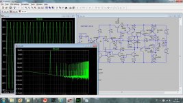
FFT at 3 volts output on 4 ohms resistive load :

Of course that the open loop gain can be increased to more than 110 db by decreasing the emitter ltp R2 and R3 and increase the C miller by the same amount for stability.
By increasing the open loop gain the thd can be reduced under 0.000x but the thd is low enough .For example most of the people can't make difference under 3 % of harmonic thd !
But I don't like the sound of the amps with increased miller cap .
So I prefer a miller cap comparable with the vas cob and a smaller open loop gain .
Like I said the fft and thd is measured with 28mA on the emitter resistors on power stage(10 from driver+18 from power bjt) .The sziklai output has for low idle currents the same thd compaired to the EF which needs 5 times more current for the same thd ! So this is a green amplifier")
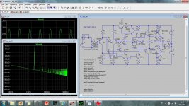
Let's go further to the ac analysis :
open loop gain from inverting input, without cfb :

with cfb from inverting input:

and in closed loop:

Of course that the open loop gain can be increased to more than 110 db by decreasing the emitter ltp R2 and R3 and increase the C miller by the same amount for stability.
By increasing the open loop gain the thd can be reduced under 0.000x but the thd is low enough .For example most of the people can't make difference under 3 % of harmonic thd !
But I don't like the sound of the amps with increased miller cap .
So I prefer a miller cap comparable with the vas cob and a smaller open loop gain .
Like I said the fft and thd is measured with 28mA on the emitter resistors on power stage(10 from driver+18 from power bjt) .The sziklai output has for low idle currents the same thd compaired to the EF which needs 5 times more current for the same thd ! So this is a green amplifier
Let's go further to the ac analysis :
open loop gain from inverting input, without cfb :
with cfb from inverting input:
and in closed loop:
Last edited:


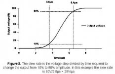
Your FFT says nothing, to get lower threshold, shorten input capacitance. To measure slew rate it should be taken simmetrically +- 90% of the square wave amplitude.
What do you want more from FFT ? lower threshold about what ?
Here is the measurement of the rise time and slew rate with input filter with a Lecroy scope and also without cfb ,only vfb .The cfb will dicrease the rise time with 100ns .
From here you can see that the rise time is linear between +-90% which means the SR is the same .

And also the appearance of the voltage feedback is delayed from the one from the current feedback with almost 400 ps .
So the cfb is faster with 0.4ns but the fastest one is setting the first feedback factor .
PS:In post nr 225 C4 is 22uF not 12pF .
Last edited:
FFT at 3 volts output on 4 ohms resistive load :
Hi Catalin
please send asc file,
thank you in advance
Your FFT shows nothing below 76dB, just short input capacitance for that simulation and you will get it below that.
Slew Rate measurement.
Dadod ,if thd shows :
Harmonic Frequency Fourier Normalized Phase Normalized
Number [Hz] Component Component [degree] Phase [deg]
1 2.000e+04 2.859e+00 1.000e+00 -2.49° 0.00°
2 4.000e+04 8.816e-05 3.083e-05 -177.94° -175.46°
3 6.000e+04 2.915e-05 1.019e-05 -85.93° -83.44°
4 8.000e+04 2.117e-05 7.403e-06 -161.72° -159.24°
5 1.000e+05 2.111e-06 7.384e-07 -31.80° -29.31°
6 1.200e+05 1.623e-05 5.676e-06 -160.35° -157.86°
7 1.400e+05 2.498e-05 8.737e-06 77.81° 80.29°
8 1.600e+05 1.248e-05 4.364e-06 -146.11° -143.62°
9 1.800e+05 4.474e-05 1.565e-05 79.16° 81.65°
10 2.000e+05 1.197e-05 4.187e-06 -140.47° -137.99°
Total Harmonic Distortion: 0.003873%
Then it doesn't matter if you have Harmonic 2 greater than Harmonic 3 or H2>H3 because you can't hear nothing under a value of 1000 greater ! For ex 3% !Try on your amp by lowering the vas load with a simple resistor and "hear" the thd .
Also by removing input cap you don't go under 73 db .
If you want to go deeper you need to change the window function to blackman or what do you need :

But remember ,at this value of thd it does not matter how the harmonics are shown,They are 1000 times lower that humans can hear ...
It matters more the phase deviation in closed loop which can be 20 degrees for ex .
The .ac and sin analysis .Like I said please be sure that the idle current is 15-20mA maximum for 2sc5200/1943 .Together with 2sc5171 we will have maximum 30 mA in 0.22 ohms
And again for dadod :

Attachments
Last edited:
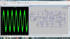
Here is what I've got with your simulation. I changed drivers and output transistors as I do not have the models for the ones you use. How do you tame output triple with no compensation whats ever? When i put 220pF between base and collector of the predrivers oscilation stops.
dado
dado
Attachments
Hello Dadod ,It seems that one of your model is not good.In my sim and more important than this,in real life on scope the amps is very stable .To design a good sziklai output you mast have bjt power+drivers with minimum cob .
I will post models which I have ,also from Cordell site .
I will post models which I have ,also from Cordell site .
Good to hear that. Did you compare side by side? I don't like the idea of using cascode and current mirror simply to achieve lower THD. I intended to build one of your amp, the one without cascode (V4.4), but first I simulated it and I found that P3A is far superior on paper so I cancelled the project.
- Status
- This old topic is closed. If you want to reopen this topic, contact a moderator using the "Report Post" button.
- Home
- Amplifiers
- Solid State
- a wonderfull sziklai