I actually built the sziklai OP stage and a little problem..
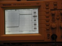
I will show it on a sim , but it does the same on the real thing.
[note "wiggle" on SW]
Self and others warned of this with the sziklai, as another
FB loop has its advantages and drawbacks (oscillation).
The fix was simple enough , a local shunt C (220p) on
each driver....
[fixed SW at 20k]
This might not be a serious problem as I could not hear any
difference in sound and my zobel network did not get hot..
but 2 caps are cheap and do the job..
[the "fix"]
Anyway, good work,catalin. I fully in tend to offer my amp
in both "flavors"(EF and sziklai) as the latter has a different
sound than the EF.
OS
I will show it on a sim , but it does the same on the real thing.
An externally hosted image should be here but it was not working when we last tested it.
[note "wiggle" on SW]
Self and others warned of this with the sziklai, as another
FB loop has its advantages and drawbacks (oscillation).
The fix was simple enough , a local shunt C (220p) on
each driver....
An externally hosted image should be here but it was not working when we last tested it.
[fixed SW at 20k]
This might not be a serious problem as I could not hear any
difference in sound and my zobel network did not get hot..
but 2 caps are cheap and do the job..
An externally hosted image should be here but it was not working when we last tested it.
[the "fix"]
Anyway, good work,catalin. I fully in tend to offer my amp
in both "flavors"(EF and sziklai) as the latter has a different
sound than the EF.
OS
Hello .I really dont'n know how do you get at these waveforms.
Do you simulate my amp or yours ?On my oscilocope the waveform (practical and theoretical) are perfect !
The success of the sziklay is to put the prefinall stage transistor with little c-b capacitance(10-20pf);the mje are not good .
If you simulate your amp I think that it hasn't phase reserve. put an pole and an zero on the diferential stage.
if you put 220pF there the slew rate will get low.So why do you design an sziklay if you get low slew rate...
Those waveforms where do you get it ??
By catalin - put an pole and an zero on the diferential stage.
That is a good idea.. R/C at differential, deal with problem
"before the fact"
We use what is available...the mje are not good
My EF shows no such effect (sim or real) so it must be
the OP.
if you put 220pF there the slew rate will get low.So why do you design an sziklay if you get low slew rate...
I used 220p just to make the point. On both the sim and
real I will "fine tune" 10-47p (or maybe none if diff. trick
works.. )The waveforms are on LT4 ...easier to show than
webcamming my CRO..
OS
At the sziklai stage, at higher frequencies, the output returns at input with 360 degrees.The "road" is by the c-b capacitance of the final bipolar and the cap of the prefinall stage.Then it a must to put in the prefinall stage bipolars with low capacitance like 2sc5171..etc. In that case(with mj) it is normal what is happening.
With those 220p you get the signal who returns at the base of prefinall stage at ground .
With those 220p you get the signal who returns at the base of prefinall stage at ground .

Test Joy200
The characteristics :
Thd = 0.001(2) at 1khz with 5 harmonics .
Slew rate measured by scope 70V/uS positive edge , 100 negative.
Bandwidth -3dB: 5Hz -- 340Khz .
Open loop Gain: 120 dB.
Closed loop Gain = 33 .
0 db frequency without input filter >14 Mhz.
Gain bandwidth product: 34e+6 .
Open loop gain at 20 khz : 65dB
Ic0 ! 25-40mA => Vr(output)~ 6-8 mV .
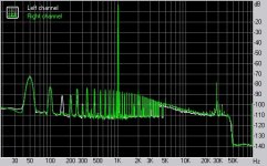
Below i tested this amp with real mark audio analizer with alc889(192 khz 32 bits) and the tda7294 ,Remember that all results are the sum of the [alc889A + one of 2 amp's] and the distortion and noise of alc889 are amplified by the amp.It may be inaccurate but it make diference between those .The load during test was a 4 ohms speakers(2 way).
The characteristics :
Thd = 0.001(2) at 1khz with 5 harmonics .
Slew rate measured by scope 70V/uS positive edge , 100 negative.
Bandwidth -3dB: 5Hz -- 340Khz .
Open loop Gain: 120 dB.
Closed loop Gain = 33 .
0 db frequency without input filter >14 Mhz.
Gain bandwidth product: 34e+6 .
Open loop gain at 20 khz : 65dB
Ic0 ! 25-40mA => Vr(output)~ 6-8 mV .
Below i tested this amp with real mark audio analizer with alc889(192 khz 32 bits) and the tda7294 ,Remember that all results are the sum of the [alc889A + one of 2 amp's] and the distortion and noise of alc889 are amplified by the amp.It may be inaccurate but it make diference between those .The load during test was a 4 ohms speakers(2 way).
Attachments
Even with the MJL's the harmonics (THD)were the same (H2/5,
no H3(see below). My slew wasn't as impressive , but that was because
of the slow drivers.
So your findings confirm mine as I compared sziklai to
EF (equal H2/3/5) both in spice and CRO (FFT, no fancy analyzer).
OS
no H3(see below). My slew wasn't as impressive , but that was because
of the slow drivers.
So your findings confirm mine as I compared sziklai to
EF (equal H2/3/5) both in spice and CRO (FFT, no fancy analyzer).
OS
Attachments
Yes but don't forget that is the real measurement and that is the sum of the (thd_alc889+gain*thd_alc889+thd_amp) !I will measure more acurate on the future.I still think that this stage is superior mos fet and ef..(for the sound and thd).
Below are the results of the alc (only).
Below are the results of the alc (only).
Attachments
catalin said:Ok ! Thank's for your feedback ! .
The others comercial amp's (up) was designed a little underrated ,no ?The engineers who design those make them underrated ?
If someone wants to listen this amp with no worries than it must 3 pairs of output devices . I must accept that the documentation about reactive load and the designing an final stage with reactive load (design about SOA vs power ) i haved miss a little.Please if you have some, maybe you can indicate to me.
I want to study all that problem in designing an proper final stage for various impedance..If you can ,give me some documentation .
Thank you again for your feedback !
A good day !
I believe you will be fine with 2 pairs like you have from a SOA perspective for 4 ohm speakers and music, that's what almost everyone selling amplifiers at this power level uses.
But without emitter resistors it will probably be unreliable! Did you check sharing during high power?
2pair 2sa1943/c5200
It's all down to adopting appropriate Vcc & Vee.
1943/5200 do not tolerate high voltages as well as other transistor types.
That's what I said.AndrewT said:Finally,.......... Fitting a 33Vac 400VA 4%regulation transformer with +-45mF on each channel turns your crippled output stage into a real 4ohm capable amplifier for domestic duty (the heatsink must remain cold).
My model still predicts 200W into 4r0 and on the 100mS 25degC soar when 55degree phase angle.
It's all down to adopting appropriate Vcc & Vee.
1943/5200 do not tolerate high voltages as well as other transistor types.
But as long as there are no emitter resistors current sharing might be so bad that it won't matter if 1 or 3 or 8 pairs is used, probably one transistor of each polarity will be taking much more load than the others. This is a much bigger problem.
Observe that at idle the current might still share well even without emitter resistors because transconductance is proportional to collector current and low at idle.
Observe that at idle the current might still share well even without emitter resistors because transconductance is proportional to collector current and low at idle.
when i was 6 years old .....
i was surprized by a loud tock tock noise created in the subway so asked my father about it and he told me that this was created by the gap between the rails that was there to prevent the rails from expanding due to summer heat ......
almost 15 years after that on my first trip abroad i was in stocholm exploring swedish ...... amplifiers he he he i realized that in swedish subway there was no gap between the lines and actually the lines were welded......
this totaly meesed me up i god all puzled and ask the first swedish engineer in front of me ( since i thought big time of my dad and he was also a mechanic , and since that was one of the first things i ve learned from him )
the mechanic said to me :
in the first years there was a gap ...now days they realized that rails may distribute the heat and expand side wise instead of lengthwise ...especially if they are welded ...... prooved my dad wrong and by the time i visit the greek subway again all lines were welded .....
what i am trying to say is that may transistors on this application do not need resistors , may the diference is converted to heat and then equally distributed to heat sink .... or may be some diference is not enough to make amplifier not working properly
but this is just an example of prospect farther testings by more experts is to be done to proove this right or wrong .....
just after next year i will produce a pcb and proceed on my own testings and let you know
happy regards !!!!!!!!!!!!!!!
megajocke said:But as long as there are no emitter resistors current sharing might be so bad that it won't matter if 1 or 3 or 8 pairs is used, probably one transistor of each polarity will be taking much more load than the others. This is a much bigger problem.
Observe that at idle the current might still share well even without emitter resistors because transconductance is proportional to collector current and low at idle.
i was surprized by a loud tock tock noise created in the subway so asked my father about it and he told me that this was created by the gap between the rails that was there to prevent the rails from expanding due to summer heat ......
almost 15 years after that on my first trip abroad i was in stocholm exploring swedish ...... amplifiers he he he i realized that in swedish subway there was no gap between the lines and actually the lines were welded......
this totaly meesed me up i god all puzled and ask the first swedish engineer in front of me ( since i thought big time of my dad and he was also a mechanic , and since that was one of the first things i ve learned from him )
the mechanic said to me :
in the first years there was a gap ...now days they realized that rails may distribute the heat and expand side wise instead of lengthwise ...especially if they are welded ...... prooved my dad wrong and by the time i visit the greek subway again all lines were welded .....
what i am trying to say is that may transistors on this application do not need resistors , may the diference is converted to heat and then equally distributed to heat sink .... or may be some diference is not enough to make amplifier not working properly
but this is just an example of prospect farther testings by more experts is to be done to proove this right or wrong .....
just after next year i will produce a pcb and proceed on my own testings and let you know
happy regards !!!!!!!!!!!!!!!
Practically I didn't test current sharing yet,I just simulate same transistor with different beta .It didn't seems that the current is different .It helps the negative reaction by the 2sc5171,1930..But as I said ,if you don't want to implement an stage protection it's better to put R in emitter ..(I'm not totaly 100% sure yet).I will calculate and simulate better when I will have time .
Excuse my english !
Before the sziklai stage I try EF a lot .That sziklay it seems to me that the heat is better than the EF.
Merry Christmas !
Excuse my english !
Before the sziklai stage I try EF a lot .That sziklay it seems to me that the heat is better than the EF.
Merry Christmas !
Hi!
A standard simulation will not show this effect because it depends on positive thermal feedback (reducing Vbe for same Ic with increasing temperature). In a standard simulation transistor junctions are all at the same temperature.
The driver stage won't help the current sharing (it can't detect differences between left and right transistors neither control them separately). If using separate drivers for each output device connected to their respective collector resistor they will force current sharing though.
Bias current will be stable in your circuit as it is set by the CFP driver. Also, bias current will probably share pretty good at idle as transconductance of output devices (and thus the positive thermal feedback) is pretty low then.
If the problem exists it might not be immediately obvious because even if sharing is way off the 1 pair doing all the work will still be able to do it for a while, but not reliably at all.
- Status
- This old topic is closed. If you want to reopen this topic, contact a moderator using the "Report Post" button.
- Home
- Amplifiers
- Solid State
- a wonderfull sziklai