Ooh, but that's not too scary compared to what I've seen on some imported cheap amps. QSC RMX1450 uses 4 pairs on +-78V and can drive 2 ohm loads (but the rails sag a lot in 2 ohms) so your amp doesn't seem extremely underdesigned at least. Also, Crest CA-4 uses 4 pairs of it's predecessors 2SC3281/2SA1302 on just above +-80V IIRC. 90V is probably pushing it though, second breakdown limit degrades pretty fast with increasing voltage!
The really bad one I've seen has 4 pairs on +-120V Actually I don't know if any amount of pairs of these is a good solution at +-120V due to second breakdown. Series connected transistors or rail switching would help a lot... The amp also has emitter resistors that are too small. The output stage doesn't have any bias normally but if the transistors were ever to heat up enough to start passing bias current it's instant thermal runaway and destruction!
Thought about using MJL2119x in that amp? I've had trouble finding them at reasonable prices though.
The really bad one I've seen has 4 pairs on +-120V
Actually I don't know if any amount of pairs of these is a good solution at +-120V due to second breakdown. Series connected transistors or rail switching would help a lot... The amp also has emitter resistors that are too small. The output stage doesn't have any bias normally but if the transistors were ever to heat up enough to start passing bias current it's instant thermal runaway and destruction!Thought about using MJL2119x in that amp? I've had trouble finding them at reasonable prices though.
current sharing
Megajocke, with Toshibas of the same batch, you have a very good matching, no need for selection. very unlike that oldies american TO-3.
About sakis circuit, you already have a good compensation of current sharing thanks to separated EMITTER (yes, in a sziklai, colectors turn to be emitters, because the master is the driver transistor) resistors combined with individual feedback resistors of 4.7R.
Mr. Douglas Self, in the book, shows a sziklai output amp (the "Load Invariant") with 2 directly paralelled transistors, yes, without any resistors!
Marcos
Megajoke
Your remarks are identical to mine. It seems you have a lot of experience about PA amplifiers... i am in this game about 25 years... many times with bitter experience from which i got the real knoweledge. Accordingly i have the sense, that it is not wise the supply level to exceeds the +/-90Vdc... for the given semiconductors on the market today. The only possibility offered to break this limit, it is the cascade.
From the other side, considering - let us to say - that we have unlimited paralleled transistors so the output can sustain any current, +/-90V supply translated in: 510Wrms/8Ù or 1020Wrms/4Ù.
Is there any speaker which needs a so high REAL power level to give its maximum SPL? Unless it has a bad designed box and crossover, which can consume the 50% of power. I have seen many times such type speakers, the most of was Hi-Fi maden from irrelevant amateurs. These guys, they confuse usually the maximum SPL obtained by a speaker regardless of the power needed.
I remember before 20 years, two guys, they sold 8 diy speakers equiped with Vifa units in a club, and i sold a Peavey CS-1000X (according to their demands in power ) and the result was broken terminal wires in woofers and burned midranges & tweeters when the people exceeded the 150 persons... of course, guilty considered the CS-1000X for the destruction ... you know from such cases.
Regs
Fotios
Your remarks are identical to mine. It seems you have a lot of experience about PA amplifiers... i am in this game about 25 years... many times with bitter experience from which i got the real knoweledge. Accordingly i have the sense, that it is not wise the supply level to exceeds the +/-90Vdc... for the given semiconductors on the market today. The only possibility offered to break this limit, it is the cascade.
From the other side, considering - let us to say - that we have unlimited paralleled transistors so the output can sustain any current, +/-90V supply translated in: 510Wrms/8Ù or 1020Wrms/4Ù.
Is there any speaker which needs a so high REAL power level to give its maximum SPL? Unless it has a bad designed box and crossover, which can consume the 50% of power. I have seen many times such type speakers, the most of was Hi-Fi maden from irrelevant amateurs. These guys, they confuse usually the maximum SPL obtained by a speaker regardless of the power needed.
I remember before 20 years, two guys, they sold 8 diy speakers equiped with Vifa units in a club, and i sold a Peavey CS-1000X (according to their demands in power
) and the result was broken terminal wires in woofers and burned midranges & tweeters when the people exceeded the 150 persons... of course, guilty considered the CS-1000X for the destruction ... you know from such cases. Regs
Fotios
Re: current sharing
I agree that matching should not be needed as you say. Seen from the outside of the sziklai you are kind of correct but inside it those are still collector resistors.
Vbe is the same for both output devices - if matched well that means same collector current will flow through both. But it is very sensitive to temperature variations and bias current. The collector resistors shown do nothing to help current share. Unless the transistor is working in its saturation region Vce chagnes won't affect the collector current much. Only base-emitter voltage and temperature matters.
The higher collector current the higher transconductance the transistors get, which means more positive thermal feedback the higher the collector current gets. At 100mA collector current the transconductance will be 4S. (Ic/Vt) This will be stable. But at 1A collector current the transconductance will be almost ten times higher giving lots of positive thermal feedback, shifting all current to one of the transistors which then will take all load because it is much hotter and has the same vbe as its parallell transistor which might not even turn on.
Adding emitter resistors of 0.22 ohms will make it impossible for transconductance to exceed ~4S, making it stable.
m2003br said:Megajocke, with Toshibas of the same batch, you have a very good matching, no need for selection. very unlike that oldies american TO-3.
About sakis circuit, you already have a good compensation of current sharing thanks to separated EMITTER (yes, in a sziklai, colectors turn to be emitters, because the master is the driver transistor) resistors combined with individual feedback resistors of 4.7R.
Mr. Douglas Self, in the book, shows a sziklai output amp (the "Load Invariant") with 2 directly paralelled transistors, yes, without any resistors!
Marcos
I agree that matching should not be needed as you say. Seen from the outside of the sziklai you are kind of correct but inside it those are still collector resistors.
Vbe is the same for both output devices - if matched well that means same collector current will flow through both. But it is very sensitive to temperature variations and bias current. The collector resistors shown do nothing to help current share. Unless the transistor is working in its saturation region Vce chagnes won't affect the collector current much. Only base-emitter voltage and temperature matters.
The higher collector current the higher transconductance the transistors get, which means more positive thermal feedback the higher the collector current gets. At 100mA collector current the transconductance will be 4S. (Ic/Vt) This will be stable. But at 1A collector current the transconductance will be almost ten times higher giving lots of positive thermal feedback, shifting all current to one of the transistors which then will take all load because it is much hotter and has the same vbe as its parallell transistor which might not even turn on.
Adding emitter resistors of 0.22 ohms will make it impossible for transconductance to exceed ~4S, making it stable.
fotios said:Megajoke
Your remarks are identical to mine. It seems you have a lot of experience about PA amplifiers... i am in this game about 25 years... many times with bitter experience from which i got the real knoweledge. Accordingly i have the sense, that it is not wise the supply level to exceeds the +/-90Vdc... for the given semiconductors on the market today. The only possibility offered to break this limit, it is the cascade.
From the other side, considering - let us to say - that we have unlimited paralleled transistors so the output can sustain any current, +/-90V supply translated in: 510Wrms/8Ù or 1020Wrms/4Ù.
Is there any speaker which needs a so high REAL power level to give its maximum SPL? Unless it has a bad designed box and crossover, which can consume the 50% of power. I have seen many times such type speakers, the most of was Hi-Fi maden from irrelevant amateurs. These guys, they confuse usually the maximum SPL obtained by a speaker regardless of the power needed.
I remember before 20 years, two guys, they sold 8 diy speakers equiped with Vifa units in a club, and i sold a Peavey CS-1000X (according to their demands in power
Regs
Fotios
Drivers made for Hifi in club speakers, with a big amplifier, and being driven by a DJ doesn't sound like a good combination
But as long as average power isn't too high (= not a DJ trying to keep the clip lights constantly on) those high powered amplifiers can be useful as speakers can take much more peak power than average power as long as duty cycle is low...
My design
Hello !
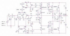
I'm smiling and I'm glad when i have seen this post.I do not know how my design reached an greek forum.The original thread is http://www.elforum.ro/viewtopic.php?f=5&t=34101&start=60, Romanian
forum.This amp is a compromise between the best sound (slew
rate, THD, phase, linearity), power consumed (it sounds better than a
amp in Class A) and the number of transistors.I wish to make this amp in mirror so it will increase the slew rate and the cross over distortion will be slower.
Your ideas are welcome .
I put resistance for the collector because I want to
implement protection in a final stage.if you don't want a protection you can put the resistor in emitor ..
Why do you want to bump 2n5401?
I attached the last version wich is more stable ,and it has more dynamics.The slew rate measured with one pair of 2sc5200/1943 was 70V/us .The thd is 0.001%.The second harmonic is almost egual with the third ..You can look at the romanian forum or if you want I can post the other measurements and results...
I named this amp JOY200 ...
Have a nice day !
Hello !
I'm smiling and I'm glad when i have seen this post.I do not know how my design reached an greek forum.The original thread is http://www.elforum.ro/viewtopic.php?f=5&t=34101&start=60, Romanian
forum.This amp is a compromise between the best sound (slew
rate, THD, phase, linearity), power consumed (it sounds better than a
amp in Class A) and the number of transistors.I wish to make this amp in mirror so it will increase the slew rate and the cross over distortion will be slower.
Your ideas are welcome .
I put resistance for the collector because I want to
implement protection in a final stage.if you don't want a protection you can put the resistor in emitor ..
Why do you want to bump 2n5401?
I attached the last version wich is more stable ,and it has more dynamics.The slew rate measured with one pair of 2sc5200/1943 was 70V/us .The thd is 0.001%.The second harmonic is almost egual with the third ..You can look at the romanian forum or if you want I can post the other measurements and results...
I named this amp JOY200 ...
Have a nice day !
Attachments
Did you check load sharing between parallell output transistors?
A good test would be expected lowest impedance dummy load, 1/2 output power (about 2/3 clipping voltage) sine wave. Measure voltage drop over collector resistors with average reading voltmeter during this test.
A cruder test would be comparing the case temperature of the parallelled power transistors when playing very loud music.
The collector resistors won't help load sharing like emitter resistors do. Even if it doesn't share it will work for a while, but don't expect it to be reliable at high power.
thanks
it is very nice to see you here .... and i apologize since i didnt know that this is your design to ask you first before posting ....
it is very nice to have you here and something is telling me that this will be a wonderfull issue to talk about ....
about SOA and fotios previous coments versus andrew t coments ....
at this point i will go with fotios .... may be andrew as usual have a detailed figure of soa of any amp ( what i like with andrew is the he never drop a comment without supporting it with data ) i find this very usefull .....
to get somewhere i mean that we have to take in mind that al these chinese amps and also crown , qsc, beringer and clones are on the street and WORKING !!!!!! so that means that andrew's estimation about SOA is correct but OPTIMUM a litle bit less prooved that didnt harm anyone ....
lets see the amp improved by the aythor now ....
thanks people
catalin said:Hello !
I'm smiling and I'm glad when i have seen this post.I do not know how my design reached an greek forum.The original thread is http://www.elforum.ro/viewtopic.php?f=5&t=34101&start=60, Romanian
forum.This amp is a compromise between the best sound (slew
rate, THD, phase, linearity), power consumed (it sounds better than a
amp in Class A) and the number of transistors.I wish to make this amp in mirror so it will increase the slew rate and the cross over distortion will be slower.
Your ideas are welcome .
I put resistance for the collector because I want to
implement protection in a final stage.if you don't want a protection you can put the resistor in emitor ..
Why do you want to bump 2n5401?
I attached the last version wich is more stable ,and it has more dynamics.The slew rate measured with one pair of 2sc5200/1943 was 70V/us .The thd is 0.001%.The second harmonic is almost egual with the third ..You can look at the romanian forum or if you want I can post the other measurements and results...
I named this amp JOY200 ...
Have a nice day !
it is very nice to see you here .... and i apologize since i didnt know that this is your design to ask you first before posting ....
it is very nice to have you here and something is telling me that this will be a wonderfull issue to talk about ....
about SOA and fotios previous coments versus andrew t coments ....
at this point i will go with fotios .... may be andrew as usual have a detailed figure of soa of any amp ( what i like with andrew is the he never drop a comment without supporting it with data ) i find this very usefull .....
to get somewhere i mean that we have to take in mind that al these chinese amps and also crown , qsc, beringer and clones are on the street and WORKING !!!!!! so that means that andrew's estimation about SOA is correct but OPTIMUM a litle bit less prooved that didnt harm anyone ....
lets see the amp improved by the aythor now ....
thanks people
Big Power Amplifier is always interesting, regardless that it's really need on the real world.
When DC Supply high voltage can reached more and more (economically) and Higher Voltage PSU Capacitor more Available Nowadays (still expensive).
Then SOA is next Problem, that in fact ,Research & development in transistor world (Higher Voltage , Ampere etc) seems stack in Place. - not to say - already reached the limit.
Next Heatsink, Wiring etc, Problem seem depend on US rather then Component itself.
we always offered to use more Amplifier unit on PA Duty from the producers (factory) , rather than Bigger output amplifier to handle huge amount of speakers.
As a DIY'ers , for ourself , then for. a little bit Commercial purpose,
I always faced to multiply BJT Output Transistor, as a part of the high demand on Bigger Power Amp in the fact.
so , as a DIY'ers isn't it challenge us ? or
we stay still until next generation Of Transistor or Electronic ?
Of Couse that Quality aproach must on the same way to go with the 'Quantity ' demand.
Really sorry , if it's look like amateurs approach or less knowledge way of view.
I don't know what do you want to say but all my amp's where tested in ruff conditions a couple of hours..2 ohmi resistence(500w)pure sine wave etc...All I'm doing I'm testing .If I'm wrong it seems that a lot of Qsc, Av ,Quad ,Ampslab ,Pss audio,Technics,Pioneer(I'm not talking about quality of this amp's ;I'm talking about quantity of final transistors..) are wrong .
I don't know why you make somuch fuzz...If you don't agree nobody is stoping you tu put another pairs or two in the final stage ....
Your approach seems to me in laudatory terms in which only came in this forum.
Have a good day !
I don't know why you make somuch fuzz...If you don't agree nobody is stoping you tu put another pairs or two in the final stage ....
Your approach seems to me in laudatory terms in which only came in this forum.
Have a good day !
catalin .....
there is no reason to be upset ...here in the forum you will listen to way too many opinions ....it is obvious that some will "judge" this or any other amp versus quality or versus power or versus stability or versus theory .or or or or or .....this is endless
if your amp could fullfill all of these critiria we are talking about some miracle !!!!!!
what i personally care about is the truth ......
for example you cannot expect this amp to power up to 500w !!!!!
you cannot expect this amp to perform squarewave to 100khz!!!
and so on and on .....
i like simple amps and this is one of them ....i bet you that it has better sonics than many presented in this forum ....
best regards sakis
catalin said:I don't know what do you want to say but all my amp's where tested in ruff conditions a couple of hours..2 ohmi resistence(500w)pure sine wave etc...All I'm doing I'm testing .If I'm wrong it seems that a lot of Qsc, Av ,Quad ,Ampslab ,Pss audio,Technics,Pioneer(I'm not talking about quality of this amp's ;I'm talking about quantity of final transistors..) are wrong .
I don't know why you make somuch fuzz...If you don't agree nobody is stoping you tu put another pairs or two in the final stage ....
Your approach seems to me in laudatory terms in which only came in this forum.
Have a good day !
there is no reason to be upset ...here in the forum you will listen to way too many opinions ....it is obvious that some will "judge" this or any other amp versus quality or versus power or versus stability or versus theory .or or or or or .....this is endless
if your amp could fullfill all of these critiria we are talking about some miracle !!!!!!
what i personally care about is the truth ......
for example you cannot expect this amp to power up to 500w !!!!!
you cannot expect this amp to perform squarewave to 100khz!!!
and so on and on .....
i like simple amps and this is one of them ....i bet you that it has better sonics than many presented in this forum ....
best regards sakis
You missunderstand.Not the output power was 500w.The load resistence has 500 w.I tested the resistence at 2ohms and 28 Vrms ...
I don't know why you make so much fuzz...If you don't agree nobody is stoping you to put another pairs or two in the final stage ....A couple of hours on 4 ohms speakers at full power didn't blow up anything.Beside that I rarely use this at full power.
.I will calculate the peak value !:
200W rms =4ohms*7Arms*7Arms
200W rms =(28Vrms*28Vrms)/4ohms
28Vrms ~ 40V at peak
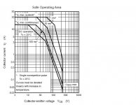
Vce at 7Arms(10A at peak)=10V.
Pdiss peak=10V*10A=100W(peak power not rms,not continuous).
On the other hand totall power disipated by the final stage is 125Wrms at full output power(200Wrms).In that case one bipolar will disipate ~32-40 Wrms (heat).
The soa of the transistor is below .
Don't forget that the prefinall stage make an negative reaction by comparing the output voltage of the output transistor .
please correct me if I'm wrong javascript:smilie(' ')
')
Why the comercial amp's have at that Vcc 2 pairs of bipolars at 200W/4ohms.They are wrong
Have a good day !
I don't know why you make so much fuzz...If you don't agree nobody is stoping you to put another pairs or two in the final stage ....A couple of hours on 4 ohms speakers at full power didn't blow up anything.Beside that I rarely use this at full power.
.I will calculate the peak value !:
200W rms =4ohms*7Arms*7Arms
200W rms =(28Vrms*28Vrms)/4ohms
28Vrms ~ 40V at peak
Vce at 7Arms(10A at peak)=10V.
Pdiss peak=10V*10A=100W(peak power not rms,not continuous).
On the other hand totall power disipated by the final stage is 125Wrms at full output power(200Wrms).In that case one bipolar will disipate ~32-40 Wrms (heat).
The soa of the transistor is below .
Don't forget that the prefinall stage make an negative reaction by comparing the output voltage of the output transistor .
please correct me if I'm wrong javascript:smilie('
')Why the comercial amp's have at that Vcc 2 pairs of bipolars at 200W/4ohms.They are wrong
Have a good day !
Attachments
catalin said:tested in ruff conditions a couple of hours..2 ohmi resistence(500w)pure sine wave etc...All I'm doing I'm testing .If I'm wrong it seems that a lot of Qsc, Av ,Quad ,Ampslab ,Pss audio,Technics,Pioneer(I'm not talking about quality of this amp's ;I'm talking about quantity of final transistors..) are wrong .
Sorry again if i look confused, but on the front of hundreds of audience in the open area. There's a real need of big and bigger power.
Maybe it's a right time to go away from Class A/B to another solution, in the pro Audio Application .
But Class A/B offers familiarity , simple and popular solution, rather than other class as DIY Kit or schematic available at the market.
So, If I look deeply disappointed then wildly multiply BJT, it because i have no other easy way yet.
Hi Cat,
I can model your output of 200W into 4r0 when driven from +-56Vdc, but only by reducing the smoothing capacitance to +-15mF and increasing the transformer regulation to 13.5%.
Yes, the model predicts that 2r0 can be driven to 302W and with this resistive load is just on the Tc=38degC soar. It easily drives 2r0 if you can keep the case temp below 38degC.
BUT, you have completely omitted to look at reactive loading.
The two pair 1943/5200 can produce 200W into 4ohm reactive 60degree phase angle and the peak dissipation is predicted at over 400W, 6.8Apk @ 60Vce. This is way outside the 10mS 38degC soar.
Into an 8ohm 60degree reactive load the model predicts 116W into 8r0 and the reactive maximum dissipation will be just over 200W, 3Apk @ 68Vce. This is just on the 100mS Tc=54degC soar.
This indicates to me that this 2pair output stage makes an excellent 8ohm capable amplifier.
I have another test for amp output.
The amp should deliver >=3 times the power into a load of half the spec resistance cf double the spec resistance. 117int 8r0 and 302W into 2r0 fails this test. indicating that current delivery into a reactive 4ohm load is inadequate.
But, 64W into 16r0 and 200W into 4r0 passes the >3times test, again confirming the 8ohm reactive load current driving ability.
Finally, having to change the smoothing capacitance and regulation to the values to match your measurements crippled the performance of this amplifier. It is crying out for a proper PSU. Fitting a 33Vac 400VA 4%regulation transformer with +-45mF on each channel turns your crippled output stage into a real 4ohm capable amplifier for domestic duty (the heatsink must remain cold).
My model still predicts 200W into 4r0 and on the 100mS 25degC soar when 55degree phase angle.
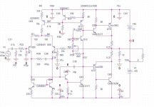
Ok ! Thank's for your feedback ! .
The others comercial amp's (up) was designed a little underrated ,no ?The engineers who design those make them underrated ?
If someone wants to listen this amp with no worries than it must 3 pairs of output devices . I must accept that the documentation about reactive load and the designing an final stage with reactive load (design about SOA vs power ) i haved miss a little.Please if you have some, maybe you can indicate to me.
I want to study all that problem in designing an proper final stage for various impedance..If you can ,give me some documentation .
Thank you again for your feedback !
A good day !
I have a little query...
When semiconductor constructors examine the SOA of a device, in which leg they place the positive voltage and in which the negative? Or in which orientation they place the DUT? In the high rail the collector and in the low the emitter, or the inverse?
I have the sense that the current during the test flows from collector to emitter because constructors reffer the measured current as Ice... is this an indication of the I course?
Regs
Fotios
AndrewT said:An Nchannel FET and an NPN BJT always have the drain/collector more positive than the source/emitter.
A Pchannel FET and a PNP BJT always have the drain/collector more negative than the source/emitter.
Thanks Andrew for the reply. I had in my mind only a NPN BJT transistor when i wrote my post. Actually, you gave a confirmation that my hypothesis was right... i talk about the current course in a NPN DUT... from collector to emitter.
I will continue in a couple of hours my further thought.
Fotios
- Status
- This old topic is closed. If you want to reopen this topic, contact a moderator using the "Report Post" button.
- Home
- Amplifiers
- Solid State
- a wonderfull sziklai