My kind of compensation
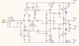
Hello, I had the ideea to amplify the miller capacitor(if the transconductance permits) by a common base stage (to have gain without phase modification) and now we gain at least 2 things :
1. The miller cap can be decreased , we gain bandwith and SR ;you can try in your amps .
2. The miller cap in DC has almost 0 potential ,from here the noise of the miller cap is reduced .
I tried on my amp and now it is very stable with the 12pF cap .Also on square wave signal .
For the moment I don't want TMC because it introduce bad behaviour with capacitive loads .
Last edited:
Hi Andrew ,
In listening test I don't see difference until now,maybe a little on the treble ,being more clear only on some parts of musical pieces .But it is just a personal opinion or a placebo-effect .I need to listen more to detect difference.
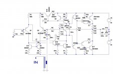
R12 is set to 10k to linearise a little the thermal deviation from BD139,we have there 0.2 mA through 10 k .In place of R13 practical there is a adjustable resistor with 5 kohm value or 1k series with 2.5k adjustable .It is shown in previous schematic ,version 4.7 and of course that is setting the current through the final stage .The resistors is a divider and is setting the voltage on the base of Bd139 .The current through BD139 is constant to 4.3mA so the divider can be calculated for the desired voltage Vce .
R 23 is setting the current of the follower bjt therefore to have the smallest noise but also with good thd so 1k for 1mA is set .Also R23 depends by R7.
R22 is there to set the maximum current through the follower and from here the maximum voltage injected in VAS .In transient signal or square wave the follower is reaching very high current which can destroy it .Therefore the maximum current is set to 3 mA with R22 .It is just a follower protected .
C1 is coming from C>1/(2*pi*f*R) where f is the lowest frequency desired and R is the 10 K input resistence .But if we want to have the gain of the filter almost 90% from the 0 db then we shoul choose a value of 6 times bigger .
I choosed a 5 hertz frequency not for the gain because I don't hear that f but I wanted a linear phase at low f .Therefore I choosed a C=6/(2*pi*5*10k)~19uF .
The other filter R11+C5 must add a small load to the preamplifier/output opamp,etc .The reactance of the cap will be 1/wC where w is 2*pi*f .F is choosed 20khz .In this case the reactance of C will be 1/(2*pi*f*C)~80k .
Therefore the smallest capacity, the smaller the load will be at high F like 20 khz , but we should not decrease it too much because we need also to limit the bandwith of the input signal .But ..
For a SACD there are some test that prove that a 50V/us per 100W power is required, therefore the input filter should not add a degradation of the SR .I calculated the filter to limit the SR at almost 100V/us .If Rail to rail voltage of the amp is 70 volt and the amp can perform 100V/us then the t rise/fall is under 1us so also the input filter should not slow down under 1 us .I choosed
a 0.6 us delay at input therefore if Time=R*C then C=T/R so 600pF would be the result .But also here to have the output voltage at 90% from 0 db then a 6 time smaller cap is good .The 6 number comes from the exponential function for 90% .
Also another advantage to choose a filter with high R and low C is that the noise and distortion of the cap is smaller compaired with a greater capacity .
I always prefer to have the smallest possible capacity by increasing the resistance in the circuits because the distortion of cap can't be simulated and also the resonance of their armatures .
In listening test I don't see difference until now,maybe a little on the treble ,being more clear only on some parts of musical pieces .But it is just a personal opinion or a placebo-effect .I need to listen more to detect difference.
R12 is set to 10k to linearise a little the thermal deviation from BD139,we have there 0.2 mA through 10 k .In place of R13 practical there is a adjustable resistor with 5 kohm value or 1k series with 2.5k adjustable .It is shown in previous schematic ,version 4.7 and of course that is setting the current through the final stage .The resistors is a divider and is setting the voltage on the base of Bd139 .The current through BD139 is constant to 4.3mA so the divider can be calculated for the desired voltage Vce .
R 23 is setting the current of the follower bjt therefore to have the smallest noise but also with good thd so 1k for 1mA is set .Also R23 depends by R7.
R22 is there to set the maximum current through the follower and from here the maximum voltage injected in VAS .In transient signal or square wave the follower is reaching very high current which can destroy it .Therefore the maximum current is set to 3 mA with R22 .It is just a follower protected .
C1 is coming from C>1/(2*pi*f*R) where f is the lowest frequency desired and R is the 10 K input resistence .But if we want to have the gain of the filter almost 90% from the 0 db then we shoul choose a value of 6 times bigger .
I choosed a 5 hertz frequency not for the gain because I don't hear that f but I wanted a linear phase at low f .Therefore I choosed a C=6/(2*pi*5*10k)~19uF .
The other filter R11+C5 must add a small load to the preamplifier/output opamp,etc .The reactance of the cap will be 1/wC where w is 2*pi*f .F is choosed 20khz .In this case the reactance of C will be 1/(2*pi*f*C)~80k .
Therefore the smallest capacity, the smaller the load will be at high F like 20 khz , but we should not decrease it too much because we need also to limit the bandwith of the input signal .But ..
For a SACD there are some test that prove that a 50V/us per 100W power is required, therefore the input filter should not add a degradation of the SR .I calculated the filter to limit the SR at almost 100V/us .If Rail to rail voltage of the amp is 70 volt and the amp can perform 100V/us then the t rise/fall is under 1us so also the input filter should not slow down under 1 us .I choosed
a 0.6 us delay at input therefore if Time=R*C then C=T/R so 600pF would be the result .But also here to have the output voltage at 90% from 0 db then a 6 time smaller cap is good .The 6 number comes from the exponential function for 90% .
Also another advantage to choose a filter with high R and low C is that the noise and distortion of the cap is smaller compaired with a greater capacity .
I always prefer to have the smallest possible capacity by increasing the resistance in the circuits because the distortion of cap can't be simulated and also the resonance of their armatures .
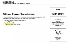
MX50-07
I'm successfully using a Chinese CFP offering outstanding stability thanks to a simple resistors separation between stages
VERY IMPORTANT: use final devices with very low hFE
LJM-Assembled MX50 SE Power amp kit Stero Amplifier boards | eBay
I'm successfully using a Chinese CFP offering outstanding stability thanks to a simple resistors separation between stages
VERY IMPORTANT: use final devices with very low hFE
LJM-Assembled MX50 SE Power amp kit Stero Amplifier boards | eBay
Attachments
Last edited by a moderator:
Hi Stee ,Here wasn't issues from the final stage .If the drivers are fast enough the CFP stage has no issues .Here the issues was comming from the fast voltage amplifier stage behind the final .Because was difficult to compensate with small capacity like 12pF with normal Miller compensation .Because with this topology I wanted to have a slew rate about 100V/us .
But now is possible with this compensation.
But now is possible with this compensation.
")

Thank you Stee ,I don't want to buy any other amp.This one is really satisfying and I am listenning every day at him .At 1 W it has 0.005% thd at 20 khz and 100V/us minimum .Also the miller cap being so small (12 pF ) it does not add any noise or distortion .Also because the potentials on the miller cap are close to 0 we don't have noise comming from the capacitor currents .
And another thing which I like at him is that with the cfp output the idle current can be only 25 mA to obtain low thd ,in comparation with EF which need more power to disipate for the same thd .
So the final stage needs in total 25mA*80V*2 = 4 Watts total disipation in stereo mode for 0.005 %thd at 20khz .
So I am happy with this one .
Last edited:
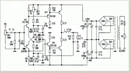
Stee's input is corrupted.
I don't know where it came from.
The LF filter is set to 200ms. That is very wideband.
The HF filter is not set to any fixed value.
At max volume the RF filter relies on the interconnect for some attenuation.
At mid volume the filter is set to 2.5us
At min volume the filter has no attenuation, but the impedance is near zero ohms and thus little interference will be able to get into the amplifier.
That nil attenuation to 2.5us is a silly arrangement.
Add 1k to 2k into the feed before the 100pF tapping point and replace the 100k attenuator with a 10k attenuator.
Personally, I would change C1 to somewhere in the range 1uF to 330nF.
I don't understand the 0r33 in the speaker connection to Audio Ground. Is this -ve output impedance?
Stee,
you should not need a simulator to notice that some of the component values and some of the arrangement gives less than optimum results.
Like reduce pot value.
Add RF attenuating resistor.
These don't come from simulator.
These come from "looking" at the flawed schematic and understanding what is supposed to happen.
Can we talk only about the Joy amp ? the working schematic which is present already from the first thread, from the beginning and updated with better performance in the past threads ?About the "Joy" amp ?
@Stee ,please if you want to present your ideas you are welcome to open a new thread .
Thank you very much!
@Stee ,please if you want to present your ideas you are welcome to open a new thread .
Thank you very much!
Why the sound is changing better ? The cfb or the low feedback ?
Hello ,I had the idea to limit the open loop gain by adding a single resistor to the amplifier and the sound has changed a lot .Now the music is played very natural and there are more details . The resistor is connected to have current feedback (about 60dB of feedback) which limit the open loop gain to less than 50 dB .Also the gain and phase from inputs to the collector's ltp are perfectly linear now.In simulation there are the same thd,imd and slew rate but the amp is sounding more enjoyable .The sound is warm compaired to the old version and very real .
All these on dynaudio contour 4 ohms speakers .
So overall we have firstly 60dB of current feedback and 20dB of voltage feedback .It is a vfb-cfb amp .It is possible also to decrease the feedback factor of the vfb by changing the R8 to 33 ohm and to decrease the R15(cfb resistor) to 33kohm .But I am extremely happy from what I hear in this topology .

The gain and phase without R from inverting input to ltp collectors :

The gain and phase with R from inverting input to ltp collectors :

Thd at 1 watt ,20khz is 0.003%,slew rate about 150V/us and the "open loop" phase is linear with 50db gain .
For these conditions the final stage is biased at 20mA +10mA from the drivers .So on 0.22 emitter resistor we have 30mA ~almost 7-8mVolts .
I enjoy a lot this sound and I don't know if I should apply all these to do a perfect simetrical topology .
Hello ,I had the idea to limit the open loop gain by adding a single resistor to the amplifier and the sound has changed a lot .Now the music is played very natural and there are more details . The resistor is connected to have current feedback (about 60dB of feedback) which limit the open loop gain to less than 50 dB .Also the gain and phase from inputs to the collector's ltp are perfectly linear now.In simulation there are the same thd,imd and slew rate but the amp is sounding more enjoyable .The sound is warm compaired to the old version and very real .
All these on dynaudio contour 4 ohms speakers .
So overall we have firstly 60dB of current feedback and 20dB of voltage feedback .It is a vfb-cfb amp .It is possible also to decrease the feedback factor of the vfb by changing the R8 to 33 ohm and to decrease the R15(cfb resistor) to 33kohm .But I am extremely happy from what I hear in this topology .
The gain and phase without R from inverting input to ltp collectors :
The gain and phase with R from inverting input to ltp collectors :
Thd at 1 watt ,20khz is 0.003%,slew rate about 150V/us and the "open loop" phase is linear with 50db gain .
For these conditions the final stage is biased at 20mA +10mA from the drivers .So on 0.22 emitter resistor we have 30mA ~almost 7-8mVolts .
I enjoy a lot this sound and I don't know if I should apply all these to do a perfect simetrical topology .
Last edited:
- Status
- This old topic is closed. If you want to reopen this topic, contact a moderator using the "Report Post" button.
- Home
- Amplifiers
- Solid State
- a wonderfull sziklai