Well, generally, I don't like to elaborate, and especially not before I tried something in practice. I can look at the simulations in (ANY) spice program ONLY as a very coarse indicator will something work or not. This proposal schematic needs to be assembled and tested prior to any further discussion.
You were right about necessity to include VAS loading resistors and decoupling from D1 anode, but R10 & R11 shouldn’t be replaced with current mirror. It should remain as is… trust me!
Because you have tried this output arrangement in practice, did you found necessity of matching of Vbe/Ic characteristics of PNP and NPN BJT-s connected to the same FET?
You were right about necessity to include VAS loading resistors and decoupling from D1 anode, but R10 & R11 shouldn’t be replaced with current mirror. It should remain as is… trust me!
I have similar amp now (FA2/3) but with BJT op, NO CM..,
WAY to much gain. Anyway , balanced VAS eliminates need for
it.
The only difference I can see no cascode on the VAS CM side,
(wilson CM instead)
but with higher rails you would never clip (saturate) anyway.
Your amp should work really good the way it is..good work.
OS
Hi LazyCat
Just to discuss your interesting design ...
It would appear that the IGBT is just a kind of "controller" for the complementary-placed BJT power transistors around it, kind of current sharing principle. In fact, the IGBT is running in ClassA, and when the current demand exceeds the quiescent current value, the BJTs cut in.
This, is, in a certain way, a sort of current dumping, as done in the Quad 405 by Peter J. Walker way back in 1975. But there he used a bridge with reactive elements to get rid of the power losses in the current sensing resistors.
It would also appear that the CCT requires a careful balance of the base current drive to the bridging BJTs, to avoid instabilities.
Nice creative work.
Thanks, and what other information do you have for us re: your circuit.
By baromega -Don't forget, that's all simulation. Take it with a pinch of... better with a handfull of salt
For the hell of it .. overdrive it (3v input)
OS
@ostripper
well, in simulator... why not, in real life... no thanks!
Here is my answer on similar question in one another thread:
"I am rarely pushing an amp into clipping because it is not primarily designed to work under such conditions. If amp is performing marvelously on all levels under onset of clipping, with good sound in any aspect and perfectly stabile, why will I ever need to push it further?! I will use it through entire "working life" of that unit well within its designed limits and it will perform as it is expected. Fact that I maybe won't know how it is behaving during clipping won't diminish my pleasure and enjoyment with that amp at all.
If your car have red zone above 6000RPM on a RPM-meter, what on Earth is suppose to force you to press accelerator pedal for more than that... except if you are interested to see engine pistons popping out through bonnet on the street!? That test, any way, won't prove that your car is not good.
Of course, that is just MY point of view... others won't have to agree!"
Dr.Bora;
May I throw in my 2 cents here ?
I play electric guitar, and one of my main criteria in my solid-state amplifiers is the behaviour during clipping, as well as the distribution of harmonics and intermodulation products.
I think too much is being made of linearity in the context of THD, whereas intermodulation seems to be completely ignored :-(.
Hi Balaboo
I agree with dr Bora on the clipping issue, why would anyone in their right mind ever want to push an amp into clipping. As for instruments I cannot comment but I can say as an ex DJ at a large discotique in my youth in the 90s we took particular care not to push our amps into clipping either. If we needed more power, larger wattage amps were the way to go, besides clipping is really bad for your hearing at power levels used in discotiques. An occasional large signal transient in a home based system is no trainsmash.
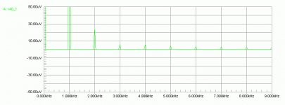
The harmonic distribution cannot get much better than Dr Bora s results, as for intermodulation I bet they are as good as the thd figures for this amp.
Dr Bora, a very good design.
homemodder said:Hi Balaboo
I agree with dr Bora on the clipping issue, why would anyone in their right mind ever want to push an amp into clipping.
An occasional large signal transient in a home based system is no trainsmash.
Hi homemodder,
Clipping is audible, yes. Clipping should be avoided, no doubt. But from my understanding and missing from these talks is the potential damage to amp components that can happen as a result of clipping. One must take steps to ensure that if clipping does occur, it doesn't destroy the amp. High frequency clipping in particular will cause large currents to flow in some devices when the design is not prepared for this.
I have started to over supply my amps, leaving some headroom to completely avoid clipping. This is probably the best approach for the DIY amp, as a higher voltage but equal VA rating transformer will not be much more expensive.
@MJL21193
“Clipping is audible, yes. Clipping should be avoided, no doubt. But from my understanding and missing from these talks is the potential damage to amp components that can happen as a result of clipping. One must take steps to ensure that if clipping does occur, it doesn't destroy the amp. High frequency clipping in particular will cause large currents to flow in some devices when the design is not prepared for this.”
Exactly MJL21193, I agree 101%. But there is another very simple solution I always advocate: if 30W of power fulfills your listening requirements, build 100W amp and don’t ever turn it to more than about 30W and enjoy! To use again analogy with cars, if you’ve purchased vehicle capable of 200km/h speed, are you suppose to drive it near that speed to justify your investment? There are people with such attitude, but most of us don’t belong to that category I believe... at least I don't!
boraomega said:@MJL21193
But there is another very simple solution I always advocate: if 30W of power fulfills your listening requirements, build 100W amp and don’t ever turn it to more than about 30W and enjoy!
Hi boraomega,
This works but it can still clip if driven with a normal signal. My method takes the input sensitivity and increases the voltage without increasing the gain so that you will only get, for example, 100 watts from an amp that is capable of 150 watts when driven to it's maximum input.
So, for a normal 80 watts amp with a PS of +/-42VDC and an input sensitivity of 1.2Vrms, you can increase the PS voltage to +/-56VDC and leave the gain alone. This will give headroom without the possibility of clipping the amp with a normal signal. Of course, you need to make sure the transistors used in the design are up to the higher voltage.
HF clipping destroys tweeters, the 8uF cap in series with a tweeter would quite happily pass 10 kHz square wave and the dc component will burn the voice coil.
In all my amps I add a clipping indicator, a very simple circuit that compares the output voltage swing with the supply. If output tends to within 5V of the rails I flash an LED. Simple but effective.


In all my amps I add a clipping indicator, a very simple circuit that compares the output voltage swing with the supply. If output tends to within 5V of the rails I flash an LED. Simple but effective.


- Status
- This old topic is closed. If you want to reopen this topic, contact a moderator using the "Report Post" button.
- Home
- Amplifiers
- Solid State
- Balanced IGBT for amplifier output


