tell us how you found the "failure/error" and how you sorted it.
Hi Andrew
Your hint re: VII Vs VIII was very helpful!!
As per Brian's suggestion, I replaced the two resistors R30 at the output, this helped to relax things.
Then I went on to do some changes:
- Replace main caps with my favorites - Mundorf MLP
- Add emitter-regenerators at the LTP
- Replace input filter to 15K and 470pF COG type, rather than 27K and 1nF disc-type ceramic.
- add 470pF COG as input compensation (bases of the LTP)
- Replace input coupling cap with 22uF AVX tant (SMD)
- Replace feedback cap with 100uF Nicicon Muse type.
- Replace rail decoupling caps with Rubicon ZL
Bias is now fixed to 13mV, translating to 30mA. Most waveforms look very well now.
Unfortunately I didn't have matching trannies to complement the output stage.
Those monos play really well now, very lively and dynamic. there is still hint of noise - around 10-20mV PTP at the output, maybe due to the open cover.
Thanks to all suggestions!
Yair
I just stumbled on this nice thread - I still use a CK1100 100w kit stereo power amp which has the 1704 modules inside if I remember correctly. I 'slung' this together sometime in the 80's. While this was always a great power amp, I did bring about major improvements in spaciousness and depth without losing a thing. I can't give specifics, but I remember measuring the DC voltages across all electrolytic caps, and found one or two that had zero DC. I replaced these with the best non-polarised ones I had around at the time. This had a major effect. The other mod was adding another 10000uF to each of the 4x4700uF reservoir caps, this helped all round a little.
I also use the CK1010 pre-amp but that's had so many mods I can't remember hardly any - probably the best one was to feed it with a pre-regulated +-15v that had lots of passive ripple filtering before it.
I know we're always listening to the whole system and not just the amp, but honestly with all my other bits and pieces like ancient Castle Conway II much modified speakers, the clarity of sound is just so amazing with this amp that I daren't ever risk 'upgrading' it.
One little problem I've had with it in one channel for 2 yrs now is a very quiet just audible at normal listening distance regular popping sound (say about 4 pops per second) after the amp has been on for an hour - turn it off and back on and it's gone for another half hour before it starts again. It's after the volume control as it's unaffected by it's setting. Probably a leaky cap, just haven't got round to fixing it.
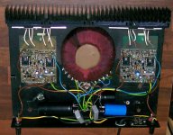
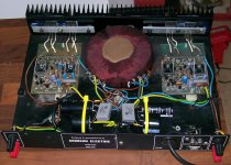
Which model is to see in the attached jpg files?
On the PCB is to read the number 35-018.
Doesn't look anything like my CK1100 with 1704 modules which have TO3 case 2N3773's on the PCB on a thick aluminium right angle mini heatsink which bolts to the main outside-world heatsink.
The Crimson 35-01 PCB had several different variants (issues) you can identify this from the number in a small square box on the PCB printing. Most were issue 5. I have an old copy of issue 6 which I have scanned and I'll upload it to my webspace in the next couple of days and repost with a link.
Most repairs can be done with a multimeter on the junction range and by spotting burnt components. Driver transistors need to be low capacitance high Ft types and a scope is needed to check there is no oscillation. Often the zobel resisitor usually R29, value 8R2 is open circuit. The wirewound resisitors in the output are 0R18 but should only be replaced if unusable as they are inductive and help with output stage stability. Diodes in the collectors of the protection transisitors were usually OA47 and can be replaced with BAT85. If the power devices are removed make sure that the sleeved bolts go back into the same holes as shorts to the heatsink bracket can occur. A current limited PSU is esential for testing.
If all else fails I do PCB repairs and updates and they are very easy to pack and post.
I just stumbled on this nice thread - I still use a CK1100 100w kit stereo power amp which has the 1704 modules inside if I remember correctly. I 'slung' this together sometime in the 80's. While this was always a great power amp, I did bring about major improvements in spaciousness and depth without losing a thing. I can't give specifics, but I remember measuring the DC voltages across all electrolytic caps, and found one or two that had zero DC. I replaced these with the best non-polarised ones I had around at the time. This had a major effect. The other mod was adding another 10000uF to each of the 4x4700uF reservoir caps, this helped all round a little.
I also use the CK1010 pre-amp but that's had so many mods I can't remember hardly any - probably the best one was to feed it with a pre-regulated +-15v that had lots of passive ripple filtering before it.
I know we're always listening to the whole system and not just the amp, but honestly with all my other bits and pieces like ancient Castle Conway II much modified speakers, the clarity of sound is just so amazing with this amp that I daren't ever risk 'upgrading' it.
One little problem I've had with it in one channel for 2 yrs now is a very quiet just audible at normal listening distance regular popping sound (say about 4 pops per second) after the amp has been on for an hour - turn it off and back on and it's gone for another half hour before it starts again. It's after the volume control as it's unaffected by it's setting. Probably a leaky cap, just haven't got round to fixing it.
Hi
I have added the earlier CPR1 preamp PCB schematic to my webspace http://homepage.ntlworld.com/bepowell/schematics/CPR1.pdf
If you have the later CPR2 PCB it can be repaired and upgraded. The most important thing is to disable the high pass filter in the line stage which made the bass light (-3db 21 Hz).
I do repairs etc to these PCBs should you need it. I shall be adding the CPR2 shematic to my webspace sometime soon.
Regards
crimson 35-01B problems
Hi
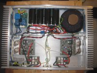
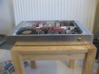
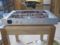
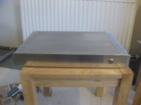
I have just managed to screw up one of my power amp modules. It's a version 3. I had completed moving them to a new case but I forgot to put one of the earth leads on. Had obviously powered it up before I noticed and didn't discharge the capacitor before I tried to fit it. When I was fitting it the lead went under the board at the front left and earthed one of the components which I heard through the speaker. Now the sound through the right speaker is about half the level of the left. I presume i have shorted on of the transistors around Tr15. Anyone have any idea what to replace. Pictures of the new case should be attached.
Hi
I have just managed to screw up one of my power amp modules. It's a version 3. I had completed moving them to a new case but I forgot to put one of the earth leads on. Had obviously powered it up before I noticed and didn't discharge the capacitor before I tried to fit it. When I was fitting it the lead went under the board at the front left and earthed one of the components which I heard through the speaker. Now the sound through the right speaker is about half the level of the left. I presume i have shorted on of the transistors around Tr15. Anyone have any idea what to replace. Pictures of the new case should be attached.
Attachments
Crimson amp rebuild
Decided to do some checks last night. Swoped the speakers leads round and realised that there was nothing wrong with the amp and that the right speaker was the problem. Checked the resistance and one of the speakers was reading 1.5 ohm's. It looks as if one of the speakers units has gone. They have a 5 year gaurantee so hopefully it will be replaced.
Decided to do some checks last night. Swoped the speakers leads round and realised that there was nothing wrong with the amp and that the right speaker was the problem. Checked the resistance and one of the speakers was reading 1.5 ohm's. It looks as if one of the speakers units has gone. They have a 5 year gaurantee so hopefully it will be replaced.
Crimson Repairs
Hi
Sorry about the late reply!
I still do repairs/updates on Crimson. Email me on bepowell@ntlworld.com and I'll provide further details.
Regards
Brian Powell
Hi
Sorry about the late reply!
I still do repairs/updates on Crimson. Email me on bepowell@ntlworld.com and I'll provide further details.
Regards
Brian Powell
")
When the V-I limit operates continuously, the VAS sources excess current via an NPN emitter follower. The current in this transistor is sensed and switches on an NPN/PNP pair using positive feedback which imitates a thyristor. The switches on a current which collapses the voltage reference for the both VAS current sources. No current in the VAS means a "dead" output which remains latched that way until the power supply is switched off and a capacitor on the PCB discharges. As far as I know Crimson were the first to disable a solid state power amplifier without the use of fuses or circuit breakers. See http://homepage.ntlworld.com/bepowell/schematics/VII.pdf
- Home
- Amplifiers
- Solid State
- Crimson (Krimson) Amp Schematics