Hello everyone. I have come across two old amplifiers from Crimson that were put together from kits in the mid 80's. The one is 60W and the other a 100W. I believe the models are 608 and 1008 respectively. The transistors used are both Toshiba, 2N3773 and 2N3055 respectively.
I would like to get these guys running, does anyone have any info/schematics on these? Thank you in advance.
I would like to get these guys running, does anyone have any info/schematics on these? Thank you in advance.
yes, I still have 6, sold the other two.halebopp76 said:From what my friend told me, these were some of the nicest sounding amps he has heard.
They perform even better with a bigger PSU that can feed real current into real speakers.
35-0,35-0Vac 625VA into four banks of 20mF to feed a stereo pair of 1704 works well for 8ohm speakers.
The advantage of the 1704 is the limiters are set for 2r7 rather than 5r4 giving peak current ability of ~15A. The filter on the protection allows even higher transient currents when demanded. It just happens that a nominal 8ohm severe reactance speaker can draw about 42/8/0.35~15Apk. The 4r0 loading and 2r7 limiting spec are just about ideal for most 8ohm speakers.
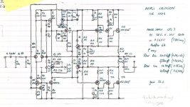
Thank you for that schematic.Hi Halebopp76,
I got two CE1004 and this schematics may help.
Higher definition schematics through email.
I need a complete overview of all models, amp modules and associated schematic diagrams of Crimson's legacy (resp. vintage) and currently audio devices.
Who can help me ?
Here some URLs:
http://www.audio-stereo.de/dokuments/pcrimsond.pdf (german)
http://www.aufi.co.il/amp/crimson.pdf (English)
:: the austin hifi blog ::: July 2009
Crimson HiFi - High End Verstärker bei Schappach Audio Mannheim
Home
Kundenfeedback und Pressestimmen über Crimson Verstärker (various test reviews in German and English)
Attachments
Last edited:
Hello. I am the designer of the Crimson amplifiers. Please feel free to mail me at bepowell@ntlworld.com. We do still manufacture top end hi-fi but not kit PCBs any more. I may be able to help with schematics or technical queries.
Design Philosophy
Hello Andrew.
You asked about design philosophy. Here are few ideas.
The philosophy of design for Crimson this last ten years or so has been to achieve as near as possible to the live performance. The best amplifiers are in one sense the ones you cannot hear. They have no sound of their own. When the music is produced with all the emotional content intact, then I feel I am on the right track.
It is nice to have some technical objectives that can be used to make good electronics. In the old days the “best” amplifier was the one with the lowest THD. I once met Tim Paravacini from EAR valve amplifiers and his sound was stunningly good. This is with THD of perhaps 1%? If THD has little to do with it what makes a good amplifier?
Some observations may help. Some amplifiers sound loose in the bass, they seem unable to control the speaker drive units. Some are simply veiled. Some create a mish-mash when several instruments play together. Some sound overloaded at all levels. Some are slow are unexciting.
I like to hear the spaces between notes with ability to hear the room or hall ambience affecting the way the sound tails away. I like to hear the resonance occurring inside the bodies of string instruments. I like rock bass to start like being kicked while being able to hear the envelope of the note and its nuances.
The eye is a poor optical instrument but we can see fantastically because the brain processes the signal and enhances it. The ear is similar. The 1% THD that we can hear on pure tones is the unprocessed raw perception figure. The are no clues for the brain to use to do the enhancement. On music all the clues should (!) be there and the sound map now having been processed by the brain could be 100 times sharper. Basically make ever amplifier property 100 times better than seems obvious and you have a good start.
Take a couple of parameters as examples. Take power supply rejection for instance. Normally it is thought good enough if the speakers do not hum. It is not quite the same when you imagine a music signal being non-linearly modulated with harmonics of 100 Hz. At full power there could be 20 mV of mains harmonics at the amplifier output. Also this means similar levels of really nasty rail signals finding there way into the amplifier signal path. If you were to consider the rail as an auxiliary amplifier input you would be wise to short this to ground! As you cannot do that why not just make the rail rejection really really high? It is not difficult or expensive. Secondly another “input” is the speaker. Music bounces round the room and appears time delayed and much modified as a reverse signal down the speaker cable, would you want this amplified again? Clearly not. So why not make the amplifier unilateral? This was done for RF amplifers a good while ago.
So take nothing for granted and do the experiments. For example, try all the triple emitter follower configurations and listen to them. (I have come to prefer one over the others since doing this.) Try adding or removing things. This approach can lead to outcomes like a power supply to feed the power supply; which may work but be expensive. I myself must admit to going down this path in the 1980s and making preamps with battery PSUs! It is better to find why the original supply did not do the job (or why the circuit failed to reject its signals and ripple) and the correct the problem at source.
Bad amplifiers come about in part because people fail to appreciate how good the human brain is. You may well have a quantum computer in there and fooling it into thinking that music is live and not recorded is not that easy.
Bad amplifiers come about in part because people fail to appreciate how good the human brain is.
Cool... Knowing that the electronics part of amplifier design is not at all a rocket science, we must already know by now what is required from an amplifier designer to be able to design best amplifiers.
That is a very encouraging philosophy from a commercial designer's point of view. We DIYers are often unable to grasp the aims and methods that led to particular commercial products and their success. It's great then, to hear the similarities with many views expressed here, in our problems, aspirations with projects and of course, the whole audio experience.
Thanks indeed for sharing. Perhaps you'd care to expand on the triples issue, regarding say, the relative benefits of the beta, crossover region width etc. Any help is good help for many here.
Thanks indeed for sharing. Perhaps you'd care to expand on the triples issue, regarding say, the relative benefits of the beta, crossover region width etc. Any help is good help for many here.
Dave (and other Crimson owners)
On this link you will find the VII schematic. By far the majority of our kits used this PCB. They are not easy to repair and a current limited PSU is essential. Crimson still do service work for all PCBs back to 1976.
http://homepage.ntlworld.com/bepowell/schematics/VII.pdf
Regards
Brian Powell
On this link you will find the VII schematic. By far the majority of our kits used this PCB. They are not easy to repair and a current limited PSU is essential. Crimson still do service work for all PCBs back to 1976.
http://homepage.ntlworld.com/bepowell/schematics/VII.pdf
Regards
Brian Powell
Hi Brian
Could you please check your mail?
I have a 630D VIII that has gone bonkers, with loud oscillations and over-heated output stage.
The oscillations stop only if I fix the bias to a very low 1mV across the R22 resistors, but then I get pretty bad distortion on 20KHz sine input.
Any suggestions?
Thanks!
Yair
Hi
I have some opinions on specific sound distortions perceived by the brain, not so much reflected in typical THD figures. Distortions in phase are quite audible, in that it affects the sound stage, particularly those non-linearities in the frequency domain including inter-modulation distortion. This makes sense if your an animal aurally evolved to determine locations of sounds. Early voltage distortion may disrupt sound perception as well. I try to avoid high DA caps in the signal path if all possible. If this means adding an extra stage for current gain because I want to use PPMF 1uf input cap, it is an acceptable compromise. For loop compensation the COG type SMD caps are very good. I think adequate damping is important as is PS rejection. This is one reason I like the HEC amplified diode based follower stage. With a seperate regulated supply for the input/VAS, the PS noise becomes part of the error signal and is nullified. Even with mosfets you can get very low output Z and it presents a very high Z load to the VAS stage. One very important concept is proper PCB layout. Laying a high current rail track next to or below a high Z signal trace is sure to bring you problems.")
I have some opinions on specific sound distortions perceived by the brain, not so much reflected in typical THD figures. Distortions in phase are quite audible, in that it affects the sound stage, particularly those non-linearities in the frequency domain including inter-modulation distortion. This makes sense if your an animal aurally evolved to determine locations of sounds. Early voltage distortion may disrupt sound perception as well. I try to avoid high DA caps in the signal path if all possible. If this means adding an extra stage for current gain because I want to use PPMF 1uf input cap, it is an acceptable compromise. For loop compensation the COG type SMD caps are very good. I think adequate damping is important as is PS rejection. This is one reason I like the HEC amplified diode based follower stage. With a seperate regulated supply for the input/VAS, the PS noise becomes part of the error signal and is nullified. Even with mosfets you can get very low output Z and it presents a very high Z load to the VAS stage. One very important concept is proper PCB layout. Laying a high current rail track next to or below a high Z signal trace is sure to bring you problems.
tell us how you found the "failure/error" and how you sorted it.Quick update: 630 monos now sorted
Brian Powell
Nice to see Brian Powell & Crimson still around, & posting
I have 2 x CE1008's with big power supplies in a 19 inch rack mount unit i put together, a "few" years ago. Still going strong
Had to repair the driver & output stages twice on one board, but apart from that all good ! Not complaining though after all these years of almost daily use. Several times they were even used for disco duties when other amps failed !
Nice to see Brian Powell & Crimson still around, & posting
I have 2 x CE1008's with big power supplies in a 19 inch rack mount unit i put together, a "few"
years ago. Still going strong Had to repair the driver & output stages twice on one board, but apart from that all good ! Not complaining though after all these years of almost daily use. Several times they were even used for disco duties when other amps failed !
Thank you very much for this informations. This seems to base on an Ouad 303 triplet in an improved version. Still very critical for unwanted oscillation problems.Dave (and other Crimson owners)
On this link you will find the VII schematic. By far the majority of our kits used this PCB. They are not easy to repair and a current limited PSU is essential. Crimson still do service work for all PCBs back to 1976.
http://homepage.ntlworld.com/bepowell/schematics/VII.pdf
Regards
Brian Powell
In the thread
http://www.diyaudio.com/forums/solid-state/113943-quad-303-triple-cascade.html
by post #20 I ask for basiclly methods/procedures and basic articles about such three stage super ß quasi complementary stages.
In this case also this thread could be of interest:
http://www.diyaudio.com/forums/solid-state/162310-how-identify-quasi-complementary-amplifier.html (post #6)
http://www.diyaudio.com/forums/soli...-models-quasi-complementary-power-output.html
Last edited:
- Home
- Amplifiers
- Solid State
- Crimson (Krimson) Amp Schematics