I built my power amp from two Crimson 35-01b modules back in 1980, and they have provided sterling service until two days ago, when fortunately my speaker fuse saved my speaker. One channel has gone DC to about 30v and stayed there.
Searching for schematics brought to me this thread on this site, and it was good to see Brian Powell posting here. Unfortunately, I haven't had any joy yet to access any schematics, beyond the hand-drawn one on the first page, which is not for my specific revision [3]. All of the promising looking links to ntworld/.../brian/... are dead, or at least not accessible to me, and his email comes back as undeliverable. I do hope this is a technical issue, and that Brian is still with us.
While I can trace the circuit (given a huge leg-up by the schematic on page 1) and I do have a working channel for reference, it would still be a great help if anybody could help me out with a schematic for the specific rev 3 boards I have.
I Can´t open the page.Dave (and other Crimson owners)
On this link you will find the VII schematic. By far the majority of our kits used this PCB. They are not easy to repair and a current limited PSU is essential. Crimson still do service work for all PCBs back to 1976.
http://homepage.ntlworld.com/bepowell/schematics/VII.pdf
Regards
Brian Powell
Crimson Elektrik CE1004 Issue 2
I recently bought a home-built Crimson Amplifier which is based on very early CE1004 Issue 2 modules with the 35-01B PCB's (circa 1977). It is working and sounds pretty good but I have stripped out the thin wiring and intend to up-grade the PSU rectifiers/capacitors, which was the original 2 x 4700uF and 6A rectifier. After 1993, one of the modules was repaired with newer output transistors 2N3773, while the other has the original BDX60 transistors. As I am doing a major overhaul on the amplifier, it makes sense to replace all the electrolytics on the modules and possibly replace the BDX60 with 2N3773. It would also be good to implement any component revisions at the same time, to bring the modules up to a later issue. Does anyone have a revision component list for the Issue 2 module? I have all the information on this thread and looking through the details, it looks like I can probably revise up to 35-01 Issue 5 or 6 which is very useful. If the hand-drawn schematic at the start of the thread is a later version than Issue 2 then that would be a good place to start.
I recently bought a home-built Crimson Amplifier which is based on very early CE1004 Issue 2 modules with the 35-01B PCB's (circa 1977). It is working and sounds pretty good but I have stripped out the thin wiring and intend to up-grade the PSU rectifiers/capacitors, which was the original 2 x 4700uF and 6A rectifier. After 1993, one of the modules was repaired with newer output transistors 2N3773, while the other has the original BDX60 transistors. As I am doing a major overhaul on the amplifier, it makes sense to replace all the electrolytics on the modules and possibly replace the BDX60 with 2N3773. It would also be good to implement any component revisions at the same time, to bring the modules up to a later issue. Does anyone have a revision component list for the Issue 2 module? I have all the information on this thread and looking through the details, it looks like I can probably revise up to 35-01 Issue 5 or 6 which is very useful. If the hand-drawn schematic at the start of the thread is a later version than Issue 2 then that would be a good place to start.
Attachments
Hi. Sorry for the slow reply I have been away. The PCBs do look about 1977. We did not use many of the TIP type driver transistors as they were not very stable. This link is to some of the Crimson schematics. Dropbox - CrimsonSchematics
Updating beyond issue 2 is not really feasible as the PCB print is different. However, I do have stocks of parts and of later used PCBs which I remanufacture. The type VII (Roman 7) PCBs are the latest ones using the TO3 metal can devices, and they do sound better than the older ones.
Updating beyond issue 2 is not really feasible as the PCB print is different. However, I do have stocks of parts and of later used PCBs which I remanufacture. The type VII (Roman 7) PCBs are the latest ones using the TO3 metal can devices, and they do sound better than the older ones.
Hi Brian,
Thanks for your response and the complete detailed design history of the amplifier modules. Its a tribute to your original design that so many of these amplifier modules are still in daily use and sound good enough to compete favourably with more modern amplifier designs. I have the original purchase receipt from November 1977 and type-written construction detail, when laser and ink-jet printers were few and far between. It looks like I can upgrade to Issue 5/6 easily and thanks for the heads-up on the TIP transistors, they will get up-graded too. The change to Issue 7 looks like a significant step change in the design but I have become fairly adept with a Dremel and a 0.8mm drill so anything is possible, pcb space permitting. I will re-build the amplifier and modules to the latest design possible but its good to know that I can replace the modules with the latest ones to achieve the best possible sound.
Thanks for your response and the complete detailed design history of the amplifier modules. Its a tribute to your original design that so many of these amplifier modules are still in daily use and sound good enough to compete favourably with more modern amplifier designs. I have the original purchase receipt from November 1977 and type-written construction detail, when laser and ink-jet printers were few and far between. It looks like I can upgrade to Issue 5/6 easily and thanks for the heads-up on the TIP transistors, they will get up-graded too. The change to Issue 7 looks like a significant step change in the design but I have become fairly adept with a Dremel and a 0.8mm drill so anything is possible, pcb space permitting. I will re-build the amplifier and modules to the latest design possible but its good to know that I can replace the modules with the latest ones to achieve the best possible sound.
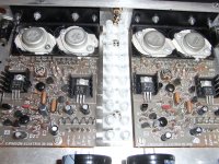
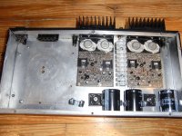
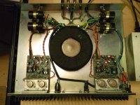
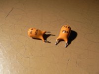
No progress on the CE1004 Issue 2 upgrade but in the meantime I picked up another Crimson amp going cheap on eBay, a CK1100 with the later CE1704 Issue VII modules. The plan was to listen to this one while I worked on the other amplifier, simples! I did my usual safety checks first (internal inspection, earth leakage, DC PSU rails and output DC offset) and found one channel was faulty, giving a very unhealthy -1.6V DC on output. Ah, that's why it was so cheap ") , I went back to the seller for a reasonable discount and set about repairing. Well to cut a (very) long story short, it took me several hours to fault-find and I was just about to give up and phone a friend (probably Brian!) when I had a flash of inspiration, replaced the 100uF 3V tantalum in the feedback path. Viola! No large DC offset and a much healthier 20mV output so all good. The tantalum must have been very leaky and this upset the DC balance of the input LTP - one to watch out for if you encounter a similar problem. I then replaced the other channel tantalum and all the electrolytics, adjusting the +VE rail dc current to 20mA, as recommended by Brian. The amplifier is up and running now and sounds very good indeed, now no more excuses for not getting back to the Issue 2 upgrade
, I went back to the seller for a reasonable discount and set about repairing. Well to cut a (very) long story short, it took me several hours to fault-find and I was just about to give up and phone a friend (probably Brian!) when I had a flash of inspiration, replaced the 100uF 3V tantalum in the feedback path. Viola! No large DC offset and a much healthier 20mV output so all good. The tantalum must have been very leaky and this upset the DC balance of the input LTP - one to watch out for if you encounter a similar problem. I then replaced the other channel tantalum and all the electrolytics, adjusting the +VE rail dc current to 20mA, as recommended by Brian. The amplifier is up and running now and sounds very good indeed, now no more excuses for not getting back to the Issue 2 upgrade
, I went back to the seller for a reasonable discount and set about repairing. Well to cut a (very) long story short, it took me several hours to fault-find and I was just about to give up and phone a friend (probably Brian!) when I had a flash of inspiration, replaced the 100uF 3V tantalum in the feedback path. Viola! No large DC offset and a much healthier 20mV output so all good. The tantalum must have been very leaky and this upset the DC balance of the input LTP - one to watch out for if you encounter a similar problem. I then replaced the other channel tantalum and all the electrolytics, adjusting the +VE rail dc current to 20mA, as recommended by Brian. The amplifier is up and running now and sounds very good indeed, now no more excuses for not getting back to the Issue 2 upgrade Attachments
hello BrianHi. Sorry for the slow reply I have been away. .
sorry also for the late response.
you helped me four years ago for one of your preamps and life made me forget to answer you and to say thank you.
so with a lot of delay, THANK YOU! :à votre santé:
hi Kay, on the CE1704 Issue VII R30 is a 2R2 resistor in parallel with L1, a 3A 3.9uH inductor. These components are for HF stability. On previous issue boards, R30 was marked as a 0R22 resistor but the wire-wound component on the board would also have some inductance too, so effectively providing a similar effect. Yes, the input/output connection pins are very close together on the bottom right-hand side of the board.
Hello
In the early 80's I've buy a Crimson amp kit model CE608, it was sounding very good.
I had others amps since and made few diy amps.
I would like to modify my Crimson amp kit CE608 to a 120 watts amp for a friend, I will replace the 2N3055 by MJ15003, and the BD140 by MJ15033.
What would be the new values for R7, R13, R15, R16 for the protection section ?
I include the modified schematic, any suggestions are welcome, tell me if there's any error.
Thank you
Bye
Gaetan
Attachments
Hi Gaetan, i assume that you simulate the circuit in LTspice to check performance. There are probably more experienced Crimson users on this forum than me but referring to my CK1100 amplifier with the 1704 Issue VII modules, R15=R16=180R and R7=R13=390R. For reference, the power supply on this amplifier measures approx. +/- 47V DC rails so pretty close to your 52V supply.
I notice your build is slightly different from the "standard" Crimson configuration i.e. there would usually be a 1u - 2u2 filter capacitor across R15/16 to reduce protection sensitivity to musical transients. Also, the schematic for Issue VII published by the circuit designer (see previous posts) does have some easy to implement improvements that might be worth considering. I would also consider increasing the power supply decoupling capacitors C2/C3 to between 47 -100uF, especially if you have longish supply lines from your PSU. The value of L1 (100uH) looks very large and must have a significant effect on the high frequency response, especially into 4 Ohms or a typical 8 Ohm speaker. The published circuit details a 3A 3.9uH inductor in parallel with a 2R2 peak damping resistor. Also BC182B is basically a 50V VCE transistor and you are running from a higher rail voltage. This circuit may simulate OK in LTspice but i have some doubts it would sound as good as it could or work reliably.
I notice your build is slightly different from the "standard" Crimson configuration i.e. there would usually be a 1u - 2u2 filter capacitor across R15/16 to reduce protection sensitivity to musical transients. Also, the schematic for Issue VII published by the circuit designer (see previous posts) does have some easy to implement improvements that might be worth considering. I would also consider increasing the power supply decoupling capacitors C2/C3 to between 47 -100uF, especially if you have longish supply lines from your PSU. The value of L1 (100uH) looks very large and must have a significant effect on the high frequency response, especially into 4 Ohms or a typical 8 Ohm speaker. The published circuit details a 3A 3.9uH inductor in parallel with a 2R2 peak damping resistor. Also BC182B is basically a 50V VCE transistor and you are running from a higher rail voltage. This circuit may simulate OK in LTspice but i have some doubts it would sound as good as it could or work reliably.
Last edited:
Hi Gaetan, you have made a few modifications but should really try to understand the basic limitations of this early amplifier design by reading D.Self and/or B.Cordell audio amplifier design books, a good place to start. Adding C10, R32, D3 to the +ve IPS/VAS rail wont do much apart from introduce drive asymmetry. The input IPS bias current is quite low 0.6V/1k = 600uA and it is not shared equally between the input diff amplifier transistors, leading to higher distortion and the low tail current might adversely affect the slew-rate limit. Unless you tackle these issues and others (e.g. no degeneration on the input transistors), you are only scratching the surface in terms of better performance. Also, the designer recommends a lower bias current of around 20mA measured in the +ve DC supply and not output stage.
Hello
I know few good amp who use the C10, R32, D3 topology, it's keep the input and vas more stable wen to output use lot of power and wen the power supply do not response fast enough.
I just fund today the original Crimson 608 schematic sent to me by Crimson elektrik.
Here it is.
Thank
Bye
Gaetan
I know few good amp who use the C10, R32, D3 topology, it's keep the input and vas more stable wen to output use lot of power and wen the power supply do not response fast enough.
I just fund today the original Crimson 608 schematic sent to me by Crimson elektrik.
Here it is.
Thank
Bye
Gaetan
Attachments
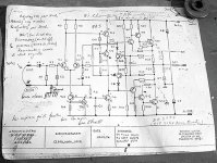
Hi Gaetan, this is the circuit configuration for an early Issue 3 or Issue 4 35-01B Crimson Elektrik PCB, according to the designers documentation earlier in post #65. From Issue 5 onwards, a latching VAS-overcurrent protection circuit was implemented in addition to the simple VI output protection. You can refer to the published VII620_630.pdf which gives actual component values and easily modify the input LTP stage and output triple stage component values to up-date these parts to the later design version. Notice that your D1 and D2 are BAT85 and not 1N4148. The designer has already said that the later board versions sounded much better. However, it would be good if you report back your success in modifying the boards and how the amplifier sounds.
Last edited:
Decoupling Capacitors
As the decoupling and signal capacitors share a common ground on the PCB, I should stick to less than 4.7 uF. Even 30 cm of PSU cable does not cause any problems, but you will need an adequate wire gauge.
The capacitor that delays the protection circuit slightly (C11) causes oscillation and is best omitted.
Regards
Brian
Hi Gaetan, i assume that you simulate the circuit in LTspice to check performance. There are probably more experienced Crimson users on this forum than me but referring to my CK1100 amplifier with the 1704 Issue VII modules, R15=R16=180R and R7=R13=390R. For reference, the power supply on this amplifier measures approx. +/- 47V DC rails so pretty close to your 52V supply.
I notice your build is slightly different from the "standard" Crimson configuration i.e. there would usually be a 1u - 2u2 filter capacitor across R15/16 to reduce protection sensitivity to musical transients. Also, the schematic for Issue VII published by the circuit designer (see previous posts) does have some easy to implement improvements that might be worth considering. I would also consider increasing the power supply decoupling capacitors C2/C3 to between 47 -100uF, especially if you have longish supply lines from your PSU. The value of L1 (100uH) looks very large and must have a significant effect on the high frequency response, especially into 4 Ohms or a typical 8 Ohm speaker. The published circuit details a 3A 3.9uH inductor in parallel with a 2R2 peak damping resistor. Also BC182B is basically a 50V VCE transistor and you are running from a higher rail voltage. This circuit may simulate OK in LTspice but i have some doubts it would sound as good as it could or work reliably.
Any advice on how to spot genuine Toshiba 2N3773 T03 transistors, I recently bought some on ebay and they didn’t have the lettering as in most pictures, the base seems thick enough though ?
Why not get genuine ones from Farnell ?
http://uk.farnell.com/on-semiconductor/2n3773g/transistor-npn-to-3/dp/9556745?st=2N3773
Looks like those Onsemi ones are close to end of life but they have lots of Multicomp branded ones in stock.
How's about this for validation; Vintage WESTREX Amp Amplifier | eBay
Westrex only used the best, so Brian's design must have proven itself to them.
https://www.diyaudio.com/forums/attachment.php?attachmentid=999038&stc=1&d=1637418335
Westrex only used the best, so Brian's design must have proven itself to them.
https://www.diyaudio.com/forums/attachment.php?attachmentid=999038&stc=1&d=1637418335
Attachments
- Home
- Amplifiers
- Solid State
- Crimson (Krimson) Amp Schematics