roender said:John,
Besides the fact that you have some mistakes in the schematic, the main two issues are related with highly asymmetrical clipping and headroom.
I see what you mean. Is this better?
Attachments
lineup said:
I see. You have a very good stable and clean supply.
I did not know. Was supposing a more ordinary DIY transformer & power supply.
Hi lineup,

lineup said:
Because, separated supplies can only improve a good circuit. Never be of any whatever drawback
Of course! But if you choose to use a single supply it will not be the end of the world. The improvement will be marginal at best, not day and night.
I abominated the abomination and It flys.. 1.2mhz unity gain
stable with no caps (really). All the gain is in the first stage
LPT and cascode (that is why it can do that). here is my
effort...
I added the widler buffer to your VAS CM (better VAS linearity)
and upped the VAS current to 5 mA (balances load to LPT)
It beats mine. but WOW thats alot of trannies..
OS
stable with no caps (really). All the gain is in the first stage
LPT and cascode (that is why it can do that). here is my
effort...
An externally hosted image should be here but it was not working when we last tested it.
I added the widler buffer to your VAS CM (better VAS linearity)
and upped the VAS current to 5 mA (balances load to LPT)
It beats mine. but WOW thats alot of trannies..
OS

ostripper said:I abominated the abomination and It flys..
Everyone gets in on the debauchery of roenders amp! Excellent!
Lots of wee diodes in that OS
ostripper said:Even more trannies...
OS
Yes, but less LED's! Performance to brag about also.
EDIT: Wrong chart - fixed now.
Attachments
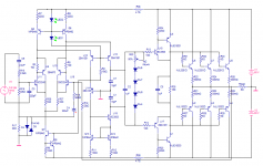
Further tinkering has produced this:

I have changed the devices in the CFP LTP to higher power and increased the current. I have also increased the current slightly through the VAS. This equates to much better simulated performance.
U1 and U5 are really 2SC4793/A1837 but I use the MJE's for simulation.
I have changed the devices in the CFP LTP to higher power and increased the current. I have also increased the current slightly through the VAS. This equates to much better simulated performance.
U1 and U5 are really 2SC4793/A1837 but I use the MJE's for simulation.
MJL21193 said:
Everyone gets in on the debauchery of roenders amp! Excellent!
Lots of wee diodes in that OS
Your jabs at people who offer complete, tested and debugged designs, that you "borrow" are really getting to be annoying and boring. You come here, people teach you then you offend them, nice, real nice ... the internet free for all, LOL!
Pete B.
jaycee said:Interesting work with a CFP input stage! Are the 2SA1381's really warranted though?
Hi jaycee,
They are dissipating ~200mW (I figure?) and they are not bad in that position. They have higher gain, high voltage and low Cob. I thought about using the 2SC3503 in place of the 2N5551's, but thought that would be truly overkill.
stinius said:MJL
I don't know why you have to change your original design, yes I know that it was "inspired" form another design but it was your design, is it because you don't wanna use LED's?
You still have a LED there, maybe you should use a CCS to power the LED?
Stinius
Hi Stinius,
No changes - the Abomination is in the books. Board layout final and all.
This is an off shoot design, a real difference from the original (RMI). I wanted to try out a few ideas and suggestions. It really doesn't have anything to do with my (fake!) dislike for LED's.
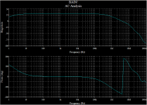
It's to be known as Bain!
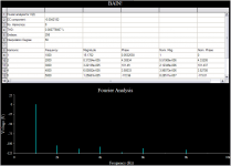
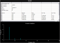
KLe said:Wow MJL21193
re: Post #71, the higher order harmonic artefacts are now below -125db
Hi KLe,
Yes, the increase in front end current has pushed THD even lower. That this is happening while not changing any of the devices used is a good indication that we could expect a similar result in the actual amp.
Also, these were taken at a medium idle current. The thermal track devices are supposed to allow a higher idle without the threat of runaway, meaning even lower high frequency distortion.
MJL21193 said:
Hi jaycee,
They are dissipating ~200mW (I figure?) and they are not bad in that position. They have higher gain, high voltage and low Cob. I thought about using the 2SC3503 in place of the 2N5551's, but thought that would be truly overkill.
Hi Stinius,
No changes - the Abomination is in the books. Board layout final and all.
This is an off shoot design, a real difference from the original (RMI). I wanted to try out a few ideas and suggestions. It really doesn't have anything to do with my (fake!) dislike for LED's.
It's to be known as Bain!
Good
I liked your first idea, maybe I would have used CCS for the LED's and a separate PSU for the first stages, but that's irrelevant.
I see that people think you are too "inspired" by the RMI, but hey all the building blocks are well known and if I'm not very wrong the RMI was also "inspired" by a well known design.
Stinius
Stinius
- Status
- This old topic is closed. If you want to reopen this topic, contact a moderator using the "Report Post" button.
- Home
- Amplifiers
- Solid State
- Abomination! or Painting a Mustache on the Mona Lisa meets the Island of Dr. Moreau