by MJL - Keep in mind that I reduced VAS current to ~2.2mA per leg to help the clipping instability problem before
Yes, at 2-3ma , the 1381's behave well. But one must
consider their intended use (video amp) and that low Cob
denotes a very small saturation prone junction. We are
building audio amps , not shortwave transmitters.
By wojtek - To Ostripper: can you try my mods and tell if that helps
I did, and they do help the sim not to crash at "gross" overdrive,
but the sticking still happens. I reduced it with circuit changes
to both amps. On the simple "blameless" 1381's behave
much better, which leads me to believe topology is as much a
factor as device choices.
I modelled the loop gain of all 3 amps (abom. ,FA2,FA1) with both
types of devices. Abomination "liked" the 1381's , Mjl's amp needs
their gain, as even with the zetex696's as input , 55db was
the most I could achieve..
") ) VERY good design, might build it
) VERY good design, might build itat a later date.) "blameless" amps also benefit from the 1381's
gain, even allowing for a non-ef'ed VAS drive with no sticking .
My latest amp works good with these devices except when overdriven, but its gain is so high (80DB) 340/50's work
just as good (topology again).
OS
ostripper said:
Yes, at 2-3ma , the 1381's behave well. But one must
consider their intended use (video amp) and that low Cob
denotes a very small saturation prone junction. We are
building audio amps , not shortwave transmitters.
Hi OS,
The VAS is that - voltage amplification stage. There is no current gain. Look at the base current and see what that is at maximum input before clipping.
Having the device on and in class A operation is what matters. Biasing it for the most attractive gain and dissipation is all you need to do.
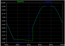
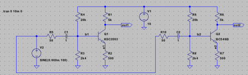
And at 100kHz curves looks almost the same (just rescaled x axis).
After commenting out QCO=... in KSC3503 model, both outputs becomes
almost the same - just at 100kHz BC546 recovers little slower from
saturation, as I expected.
... eeh to much off-topic. I'll post futher about that (if any) on separate thread.
After commenting out QCO=... in KSC3503 model, both outputs becomes
almost the same - just at 100kHz BC546 recovers little slower from
saturation, as I expected.
... eeh to much off-topic. I'll post futher about that (if any) on separate thread.
wojtek5001 said:Sorry for off-topic again, but that simple drawing shows what am talking
about.
Hi,
Yes, the real circuit wouldn't do that - it would only clip on the bottom, not the top. This is something the sim gets wrong (the one I use too).
Hi MJL
What is PSRR value of the Abomination and Bain?
Keep up the good work ... that MJL and everybody.
great job!
PS: It would be nice to have Power Regs for these excellent amps ... any ideas in this direction
1. One direction could be SMPS.
2. A Discrete Power Reg could be developed.
3. ??? ideas ???
What is PSRR value of the Abomination and Bain?
Keep up the good work ... that MJL and everybody.
great job!
PS: It would be nice to have Power Regs for these excellent amps ... any ideas in this direction
1. One direction could be SMPS.
2. A Discrete Power Reg could be developed.
3. ??? ideas ???
KLe said:Hi MJL
What is PSRR value of the Abomination and Bain?
Interesting...
PSRR should be better on Bain as it has active CS front end, but the sim shows it otherwise.
First, here is Abomination. I put .3Vrms AC in series withe the power supply, shorted the input to ground. Notice the scale highlighted in yellow. Bottom trace is output from the amp showing the amount of ripple.

Next is Bain. This surprised me because I thought it would be at least as good.

By changing the CS to LED biased improved this significantly, to equal the PSR of the Abomination. I'm curious if this is a real world thing too. I assumed that better PSR could be realized by using an active CS. Is this not the case? Is a LED bias better?
KLe said:Hi MJL
I had an idea … is it possible to run the amp without C4? That is make it DC to ground …
Hi KLe,
I wouldn't do it myself.
You could try it with and without this cap to see if you hear a difference.
roender said:John,
Negative and positive PSRR for RMI-FC100 without separate and stabilized power supply for input stage.
Now you see why is necessary a good power supply for voltage amplification stage?
Nobody complicate the design for nothing ...
Cheers,
M
Hi roender,
Did you measure it on the actual amp, or just in simulation?
I have attempted to measure it on my operating amp. This is powered with a temporary supply - 20000uF per rail only. No snubbers, nothing fancy.

This is with the input shorted to ground. Probe is at 1X and attached to the speaker output terminal. There is an 8 ohm dummy load connected.
Measured DC offset is less than 1mVDC.
Scope is at it's lowest setting. As you can see, there isn't any significant ripple present, just noise.
DMM reads less than 1mVAC on output
I think this puts a face on it. This is a real operating amp, after all.
roender said:John,
You mast be joking if you think that PSRR can be measured with a simple scope!
No joke. This is what I have available and it demonstrates the situation accurately.
How would you measure a signal through an amp? How would you see the MAGNITUDE of the signal? In order to be HEARD a signal needs a minimum magnitude.
MJL21193 said:
... it demonstrates the situation accurately.
Yes, but at DC.
What about all frequency domain?
Why don't you inject 20Khz 1Vpp sinewave trough a serial capacitor over V+ and then V- ?
roender said:
Yes, but at DC.
What about all frequency domain?
Why don't you inject 20Khz 1Vpp sinewave trough a serial capacitor over V+ and then V- ?
No, at AC.
Why? The frequency of the AC ripple here is 60Hz and any harmonics of this would be at a lower magnitude.
I don't think it's necessary to guard against that which most likely not happen.
I'm confident that this amp will be FINE without a separate, regulated supply. If this wasn't the case, I'd see the evidence on the scope. You can't hear what's not there.
MJ, the PSRR of your amp may in fact be very good, but, you seem to be just measuring residual noise. The scope will work, but you need real-world hash on the supply lines to get a true picture (specan would be nice, bu I don't have one for audio either). A few mv of hum from an unloaded supply isn't doing it. Try connecting two channels to the same supply, driving the crud out of one, the seeing what comes out the other. Lots more 120Hz than you get just sitting with one channel and the input shorted. And harmonics of the signal driving the other channel.
roender said:OK
What about back injected signal (power sagging) from output stage singing?
Noise floor??
wg_ski said:MJ, the PSRR of your amp may in fact be very good, but...
Hi wg-ski,
I'm trying to put things in perspective. That screen shot above is the actual output from a powered amp. It shows no signal magnitude.
Lets look at the supply ripple:

That's what is coming out of the supply, BUT although the scope is still at it's lowest setting the probe is set to 10X! Significant ripple, no?
This is what the amp is rejecting and not amplifying.
wg_ski said:MJ, the PSRR of your amp may in fact be very good, but, you seem to be just measuring residual noise. The scope will work, but you need real-world hash on the supply lines to get a true picture (specan would be nice, bu I don't have one for audio either). A few mv of hum from an unloaded supply isn't doing it. Try connecting two channels to the same supply, driving the crud out of one, the seeing what comes out the other. Lots more 120Hz than you get just sitting with one channel and the input shorted. And harmonics of the signal driving the other channel.
Or if you are feeling really adventurous you can return the amplifiers power supply to ground via 4 or 8 ohm resistive dummy load, and drive this resistor to, say, 10 peak, with another audio power amplifier driven from a signal generator. Sweep 10Hz-100kHz.
Cheers,
Glen
- Status
- This old topic is closed. If you want to reopen this topic, contact a moderator using the "Report Post" button.
- Home
- Amplifiers
- Solid State
- Abomination! or Painting a Mustache on the Mona Lisa meets the Island of Dr. Moreau