I always start in the power supply. Usually larger/better or additional power supply filter caps sometimes paralled with a film cap. Usually replace bridge with discreet fast/soft diodes. A little more bias is sometimes fun to play with, swapping out the pots for multi turn units helps stop the bias drift. Do this then give it a burn in and listen.
KevinLee said:I always start in the power supply. Usually larger/better or additional power supply filter caps sometimes paralled with a film cap. Usually replace bridge with discreet fast/soft diodes. A little more bias is sometimes fun to play with, swapping out the pots for multi turn units helps stop the bias drift. Do this then give it a burn in and listen.
I have the schematics, so I will try and upload it along with a photo of the inside of the amp. I can follow the schematics as to what I would need to do to any of the circuits. So if you would suggest to swap out resistors, caps, diodes,etc, I can do that.
Thanks Again!
Here is the link for the schematics:
http://s173.photobucket.com/albums/...AcurusDIA-100Schematics-1.jpg&t=1228614834766
http://s173.photobucket.com/albums/...AcurusDIA-100Schematics-1.jpg&t=1228614834766
Here is the link for the Power Supply:
http://s173.photobucket.com/albums/...-100SchematicsPowerSupp-1.jpg&t=1228615264086
http://s173.photobucket.com/albums/...-100SchematicsPowerSupp-1.jpg&t=1228615264086
KevinLee said:I always start in the power supply. Usually larger/better or additional power supply filter caps sometimes paralled with a film cap. Usually replace bridge with discreet fast/soft diodes. A little more bias is sometimes fun to play with, swapping out the pots for multi turn units helps stop the bias drift. Do this then give it a burn in and listen.
I have an Acurus 100X3 (specs 100W @ 8R, 125W @ 4R) that appears to have a similar circuit, and I would also like to beef it up, so I hope my questions will be relevant also to the DIA-100. I have not yet contacted Klipsch for my schematic. My goal is to improve the 4 Ohm power (and make the amp sound its best, obviously!).
1. I noticed the circuit has one 1k pot. Is this to adjust the bias? I don't really understand how to read a circuit. It idles stone cold (The hs is pretty much at ambient temp at idle), which I'm ASSUMING is an indication that the bias is set on the low side. How do I increase the bias?
2. Can we have a recommendation for exactly which diodes to use? I heard that 'soft recovery' was more important than 'fast recovery.' The cheapskate in me wants to just put some caps and resistors across the diodes in the existing bridge.
3. My amp has a 23mF ps cap from plus to ground and one from ground to minus, and what appears to be a 300-350VA torriodal transformer that I measured putting out 93VCT. I see that Apex Jr has a 600VA torroid that is 90VCT and 15mF caps for $3, which I'm thinking about getting and making a CRCC with 0.1-0.2R.
4. I will try to find replacements for all the on-board electrolytic caps. From looking at the schematic of the DIA-100, are there any that could benefit from a different type, increased value, or film by-pass cap?
5. Before the power switch there's a thermistor USS 2R515 (rating says 15A Imax, 2.5 Ohm at 25C, but I measured 4 Ohms) which hardly even gets warm. Isn't this a waste? It does get much warmer while playing loud.
Thanks!
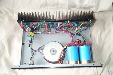
PS. Nicked a pic from ebay.
Attachments
Hi Tosh, I recently upgraded my Acurus DIA-100 amp with the following changes: First was to remove caps C-1(.1uf) & C-2(10uf) on the signal path of each board, and replaced them with 1uF Sonicap Platinum on each board. Next was to add a Black Gate WK 220uf cap along with a 1uf Sonicap Platinum (cut-lead type) in parallel with each of the Power Caps marked as C-1 & C-2 located on the power supply schematics. Last mod was replacing the bridge rectifier, making a new one using Fairchild Stealth diodes (30amp/600v). Only problem was that the 1uF Sonicap Platinum’s are fairly large caps, so the cap that went on the board closest to the A/C wires going to the on/off switch was causing a slight humming noise, and also created some A/C leakage measuring 60+ mv read at the left speaker output. To correct this, I wrapped copper foil (16awg) around the A/C wires to create a shielding effect, which I then grounded to the chassis. After the mod was complete, I fired it up, and all I can say is WOW! It should be noted that the sonicap platinum’s take some time to burn in, say around 300 hours. If your bankroll is a little shallow for this upgrade, you may want to try the Sonicap Gen I's. Also used Cardas Quad-Eutectic solder. Hope this helps out.
Emile
Emile
I have an Acurus 100X3 (specs 100W @ 8R, 125W @ 4R) that appears to have a similar circuit, and I would also like to beef it up, so I hope my questions will be relevant also to the DIA-100. I have not yet contacted Klipsch for my schematic. My goal is to improve the 4 Ohm power (and make the amp sound its best, obviously!).
Wow, this amp seems to have very little juice to handle hungrier speakers (4R)! You have to be very careful on what to load it with.
But it seems clear why's that just by seeing the photo: the transformer is very small.
So if you want to improve things, even for 8R loads, I think a transformer upgrade should be considered. At least to double that size.
Perhaps going dual mono, using a similar transformer that size on both channels might do it too.
It's no use upgrading bridges or caps in the supply if you don't feed them with enough current.
If you use just one bigger transformer for both channels, use separate bridges and caps for each channel.
1. I noticed the circuit has one 1k pot. Is this to adjust the bias? I don't really understand how to read a circuit. It idles stone cold (The hs is pretty much at ambient temp at idle), which I'm ASSUMING is an indication that the bias is set on the low side. How do I increase the bias?
You increase it by moving this pot. But this should be the last thing to do. You have to be very careful and watch the heatsinks temp, so they can dissipate the additional heat as you increase bias. Also watch the output transistors temp, just in case the heat transfer is not efficient enough. If they get hot to the touch you may need to change the isolators and use more efficient ones, or the transistors may no last.
But beware: not always does increasing bias improve things.
2. Can we have a recommendation for exactly which diodes to use? I heard that 'soft recovery' was more important than 'fast recovery.' The cheapskate in me wants to just put some caps and resistors across the diodes in the existing bridge.
Caps and resistors across the diodes may do very little. Fast soft recovery diodes seem to be the best for power amps. Just watch current is high enough.
3. My amp has a 23mF ps cap from plus to ground and one from ground to minus, and what appears to be a 300-350VA torriodal transformer that I measured putting out 93VCT. I see that Apex Jr has a 600VA torroid that is 90VCT and 15mF caps for $3, which I'm thinking about getting and making a CRCC with 0.1-0.2R.
That transformer might do it, to feed both channels.
4. I will try to find replacements for all the on-board electrolytic caps. From looking at the schematic of the DIA-100, are there any that could benefit from a different type, increased value, or film by-pass cap?
The critical caps are C2 and C7. Put the best you can afford on C2, bypassed or not (try), and check what you have on C7. If C7 is a decent one, designed for audio, just leave it: you will only do better by going for a film cap or a maybe a servo. If not try a Black Gate or something.
5. Before the power switch there's a thermistor USS 2R515 (rating says 15A Imax, 2.5 Ohm at 25C, but I measured 4 Ohms) which hardly even gets warm. Isn't this a waste? It does get much warmer while playing loud.
Maybe it's just preserving the switch from burning. I don't think I'd use it, but don't take my advice on that one.
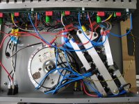
one of the things i would do .....
is to replace the banks with something else
it doesnt look too good ...the way caps are located .... i would go for smaller caps and more but most of everything Placed properly.....
as about the rest of the mods i will agree with most of them ....
looks like a nice amp but ....
i thing cooling is not enough and then the way the amp is biased is not the thing i would keep ..... i could go for something more precise
cheers sakis
FSHZ:42 said:First was to remove caps C-1(.1uf) & C-2(10uf) on the signal path of each board, and replaced them with 1uF Sonicap Platinum on each board.
Thanks for that, Emile. But won't replacing a 10uF with a 1uF cut some bass?
carlmart said:You increase it by moving this pot. But this should be the last thing to do. You have to be very careful and watch the heatsinks temp, so they can dissipate the additional heat as you increase bias. Also watch the output transistors temp, just in case the heat transfer is not efficient enough. If they get hot to the touch you may need to change the isolators and use more efficient ones, or the transistors may no last.
But beware: not always does increasing bias improve things.
The critical caps are C2 and C7. Put the best you can afford on C2, bypassed or not (try), and check what you have on C7. If C7 is a decent one, designed for audio, just leave it: you will only do better by going for a film cap or a maybe a servo. If not try a Black Gate or something.
Thanks Carlmart, I will plan on getting a bigger transformer to go along with more ps caps (but still keep it as one supply). Against your good advice, I feel the urge to play with the bias first (because I've never seen an amp idle so cold). But to adjust it equally for the 3 channels, should I measure the voltage drop across one of the 1k resistors (R20 or R21) in series with the pot and keep it the same for each channel, or is there a better way?
I'm surprised C7 is also critical, but I can see it sitting between output and ground (with R18 in between). I will leave it alone for now unless I stumble upon a suitable replacement.
hmmm
that too...... it real doesnt make any sense ( the wiring )
i presume that you understand why i dont like big caps placed like that ..... ( fluids go to only one side through th years and then you get less capacitance )
Tosh said:Sakis:
Indeed the layout is odd, especially tying all the wires together (input, ground, supply, output). I will try to sort this out when I add ps caps and swap transformer and diode bridge, at least as far as making the wiring paths a bit more symmetrical.
that too...... it real doesnt make any sense ( the wiring )
i presume that you understand why i dont like big caps placed like that ..... ( fluids go to only one side through th years and then you get less capacitance )
Thanks Carlmart, I will plan on getting a bigger transformer to go along with more ps caps (but still keep it as one supply). Against your good advice, I feel the urge to play with the bias first (because I've never seen an amp idle so cold). But to adjust it equally for the 3 channels, should I measure the voltage drop across one of the 1k resistors (R20 or R21) in series with the pot and keep it the same for each channel, or is there a better way?
You can do it, but you may have to retouch it afterwards.
Perhaps the instructions below may help you:
http://users.tpg.com.au/users/gerskine/dxamp/
I'm surprised C7 is also critical, but I can see it sitting between output and ground (with R18 in between). I will leave it alone for now unless I stumble upon a suitable replacement.
IMHO that capacitor may have more importance than the one at the input, because it affects the feedback.
Re: hmmm
I thought you were talking about the ps caps' distance away from the pcbs.
But now that you mention it, it would make it tidier if the original and new ps caps I'll be adding were all oriented up, so I can make a nice big ground bar across them all.
Come on, Sakis?! Just how gullible do you think I am? No wonder it sounds better when I have the amp standing on its side! What if I swap them around every couple of years? Just what I needed: something new to worry about...sakis said:i presume that you understand why i dont like big caps placed like that ..... ( fluids go to only one side through th years and then you get less capacitance )
I thought you were talking about the ps caps' distance away from the pcbs.
But now that you mention it, it would make it tidier if the original and new ps caps I'll be adding were all oriented up, so I can make a nice big ground bar across them all.
Re: Re: hmmm
constructing one amp ore restoring one is a list of do's and dont's...
i ll give you an example .....in yamaha amp aged like hell (25-30years)CA 400 may be 40+40 W do you think that worth :
---to recab banks from 2x4700 to 2x10.000 mfd
---relocate zobel in the out put
---match and common heatsink on LTP stage
---add multi turn to idle
--- create a start ground and seperate the box from it
---rewire and replace poor signal cables
--- rewire and replace speaker's cables ( actually rewire them
away from ac 220 volts cables)
---- remove speakers A/B switch
---- recap the all unit add by passed decoupling
---- replace fuse holders and fuses
well first of all if the costuemer pay for it then yes worth the trouble ...... then again if you measure the amp before and after the changes are astronomical .....and most of all it WAS FUN TO DO !!!!!!!
in your case and for such an amp of course makes sense to rewire ..... to replace caps not only as un upgrade but also as a position
friendly regards sakis
Tosh said:
Come on, Sakis?! Just how gullible do you think I am? No wonder it sounds better when I have the amp standing on its side! What if I swap them around every couple of years? Just what I needed: something new to worry about...
I thought you were talking about the ps caps' distance away from the pcbs.
But now that you mention it, it would make it tidier if the original and new ps caps I'll be adding were all oriented up, so I can make a nice big ground bar across them all.
constructing one amp ore restoring one is a list of do's and dont's...
i ll give you an example .....in yamaha amp aged like hell (25-30years)CA 400 may be 40+40 W do you think that worth :
---to recab banks from 2x4700 to 2x10.000 mfd
---relocate zobel in the out put
---match and common heatsink on LTP stage
---add multi turn to idle
--- create a start ground and seperate the box from it
---rewire and replace poor signal cables
--- rewire and replace speaker's cables ( actually rewire them
away from ac 220 volts cables)
---- remove speakers A/B switch
---- recap the all unit add by passed decoupling
---- replace fuse holders and fuses
well first of all if the costuemer pay for it then yes worth the trouble ...... then again if you measure the amp before and after the changes are astronomical .....and most of all it WAS FUN TO DO !!!!!!!
in your case and for such an amp of course makes sense to rewire ..... to replace caps not only as un upgrade but also as a position
friendly regards sakis
I see! It is an 'RGA'-branded 220uF 25V NP that looks fairly ordinary. Perhaps I will squeeze in a couple of 470uF 16V Nichicons soldered end-to-end to make them non-polar? (Does it matter which ends - plus or minus - face out?)carlmart said:IMHO that capacitor may have more importance than the one at the input, because it affects the feedback.
Klipsch emailed me the schematic for the A100X3 (which is an update over my 100X3), but it is essentially the same as the DIA-100, so I'll keep referring to the DIA-100 here. (Especially as this is FSHZ:42's thread! How's your DIA-100, Emile?)
Sakis, I had a recent similar upgrade experience myself on my cheapie Pioneer DV-250 DVD player (and I'm not even done yet). I am aiming to make changes to this amp in small steps so I can hear the effect of each change.
I now have a ~500VA 80VCT toroidal transformer onto which I can wind additional voltage. Should I just aim for the original's ~93VCT?
Going back through this thread I realized it has been mentioned twice to use >multi-turn< pots for the bias. Is it that important? I might as well do it when I have the pcb out? I won't play with the bias until I make some new heat sinks, for which I have big plans. By the way, how is the DC offset adjusted on these?
One of the small differences between the 100X3 circuit and DIA-100 circuit is that R1 (100k between positive input and signal ground) on 100X3 is not before the input caps C1 (0.1uF film bypass) and C2 (10uF electrolytic), but afterward, so I could actually replace C2 with a film cap at the input RCA socket. Would there be a downside to this (as there are many inches of signal wire to get to the pcb)?
Thanks for all the help!
Klipsch emailed me the schematic for the A100X3 (which is an update over my 100X3), but it is essentially the same as the DIA-100, so I'll keep referring to the DIA-100 here. (Especially as this is FSHZ:42's thread! How's your DIA-100, Emile?)
Hi Tosh, My DIA-100 is still playing really well! It seems to get a little better with more break-in hours. This upgrade was well worth the cost! As I described in my last post, this upgrade was actually thought out by Jeff Glowacki from Sonicraft. If anyone should know how to upgrade, Jeff would be the one. Like I said, I am not sure to what extent you're willing to go, but if the Sonicap Platinum's are too costly, I would recommend trying the Gen I's.
Emile
I found some 1k multi turn Bourns at Halted Specialties. And my ps caps and film caps for input arrived from Apex Jr. So now I just need to pick out rectifier diodes.
I started making new heat sinks which have over 1.7 times the surface area of the originals.
I started making new heat sinks which have over 1.7 times the surface area of the originals.
Attachments
Done!
I finally got around to wrapping up these mods to my Acurus 100X3:
new heatsink
add PS caps 8x15000uF
add 0R25 to CRCC ps caps
new trafo (~600VA 80VCT)
new input caps: 10uF Nichicon Muse
new feedback caps: 220uF Nichicon Muse
new Bourns 10k multi-turn bias trim pots
add LEDs in cover (as light in switch is bad)
new feet
I think bumping the bias made the biggest change in sound at normal volumes. (I initially measured about 0.02-0.03A draw on the plus rail and increased it to about 0.18A with room to go still.) New input and feedback caps made the top end nicer. The extra PS caps added solidity to the bass. PS ripple went from 0.015VAC to 0.003-0.004VAC.
Attachments
- Status
- This old topic is closed. If you want to reopen this topic, contact a moderator using the "Report Post" button.
- Home
- Amplifiers
- Solid State
- Need advice for upgrading an Acurus DIA-100 amp