I have one gripe with all of these mods - you have increased the power supply's current capacity, but you have NOT considered that the output stage is now undersized... i would want more than 2 pairs of 2SA3281/2SC1302 (if ive read it right) for 60V rails into 4 ohm loads.
Ensuring supply collapse will happen before the output transistor's SOA is a common dodge practiced in commercial gear. This is undoubtedly one of the reasons why the 350VA transformer was picked. Your amp now has the current capacity in the supply to drive 4 ohm loads well, but you are now risking blowing the output transistors.
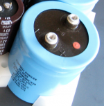
You would get a performance gain by replacing the 2 large caps with the equivalent capacitance in individual capacitors. Also add some decoupling with 470nF or so polyesters. Larger caps have higher ESR than a few smaller ones in parallel.
Ensuring supply collapse will happen before the output transistor's SOA is a common dodge practiced in commercial gear. This is undoubtedly one of the reasons why the 350VA transformer was picked. Your amp now has the current capacity in the supply to drive 4 ohm loads well, but you are now risking blowing the output transistors.
You would get a performance gain by replacing the 2 large caps with the equivalent capacitance in individual capacitors. Also add some decoupling with 470nF or so polyesters. Larger caps have higher ESR than a few smaller ones in parallel.
Hi Emile,
This amp has a lot of authority now (as the reviewers say), and with every change I could notice a slight improvement. As I said, I feel the single biggest improvement at normal volumes came from turning up the bias. So Yes, you should do this as well.
Start by disconnecting all outputs and inputs. Disconnect one rail fuse (either plus or minus side, whichever is easiest to reach) and hook a DC ammeter across the empty fuse clips. Turn on the amp and note the current drawn through meter. Mine measured only about 0.02-0.03A initially, and I kept turning the 1k pot (every 10-15 minutes in about 0.02A increments while the temperature stabilized) until it was out of travel, at which point the current was about 0.17A (and 0.18A on the other channel, which I dialed down to 0.17A so they would be the same). With your original heatsinks, you may not be able to turn it up this much without it getting too hot. On mine, I had to put in larger range pots to go above 0.17A, but I don't think you will need to do that.
Tosh
Attachments
Jaycee, the output stage is what it is, and there was never any chance that I would try to redesign the amp. And it has fuses to prevent it from trying too hard. (Even with smaller 3A fuses on each rail - stock was 4A - it hasn't blown any yet, despite my attempts.)
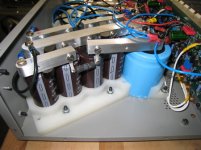
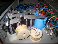
Per rail, I added 4x15000uF to the existing 23000uF, splitting it up into (15+15) + 0R25 + (15+15+23) CRC per rail and added a 10uF and 0.01uF film. Could I do better?
Per rail, I added 4x15000uF to the existing 23000uF, splitting it up into (15+15) + 0R25 + (15+15+23) CRC per rail and added a 10uF and 0.01uF film. Could I do better?
Attachments
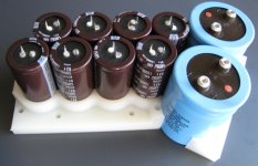
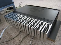
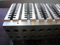
About six months ago I had turned the bias up to 0.24A, and the amp was idling nice and warm. So a few days ago I decided to shoot for 4W of class A (into 8 Ohms), and turned the bias up to 0.36A! (So that's more than 12 times the factory setting!) Warmer, but still within reason, so I reckon these new heat sinks are working pretty good.
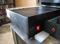
Today I finally got around to installing the new rectifiers. They get quite hot when playing very loudly, but I think they'll be fine without a heat sink. It's hard to say if they sound any different (perhaps the top end is a tiny bit better), but I'm pleased that they're in -- and that everything still works!
Today I finally got around to installing the new rectifiers. They get quite hot when playing very loudly, but I think they'll be fine without a heat sink. It's hard to say if they sound any different (perhaps the top end is a tiny bit better), but I'm pleased that they're in -- and that everything still works!
Attachments
two parralel metal plates are a capacitor the dielectric is air and all of these is also probably another capacitor if fit too close to the metal cover of your amplifier
that is why even in smaller size like a pcb proximity between traces is an issue but also impedance and sensitivity are diferent ther but principal is the same
that is why even in smaller size like a pcb proximity between traces is an issue but also impedance and sensitivity are diferent ther but principal is the same
Alright, I'll play along: At an overlap area of 1cm^2 and separation distance 2mm (both extremely worst case) between the cathode of one diode to the amp case,
C=0.44pF
I guess I'm going to have to live with that? Really good thing I didn't make a heat sink for them using some Al sheet and mica insulators or I would have increased the C by a factor of ten, maybe a hundred with some very thin mica....
And to think some people actually mount a small cap (and R) between terminals in a bridge?
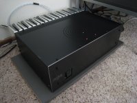
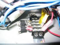
I had big plans to make a new front panel using a latching Bulgin switch, but when I actually laid hands on the switch, it was too small to reliably operate with my medium fingers, so I reluctantly sent it back to Mouser and went with plan B as seen in next pic.
So anyone with an old Acurus with a switch with a flickering green neon can add instant old-school look with this $3 perfect fit direct replacement illuminated power switch:
540-YRM32F2BBRLN Cherry red illum switch
So anyone with an old Acurus with a switch with a flickering green neon can add instant old-school look with this $3 perfect fit direct replacement illuminated power switch:
540-YRM32F2BBRLN Cherry red illum switch
Attachments
Last edited:
CRC to CLC update
I replaced the 0.25 Ohm resistors in the CRC with 18AWG 1mH inductors that have ~0.2 Ohm DCR.
before:
V rails = +/- 51.8VDC
ripple (with amps connected) = 8-10mVAC (meter not steady)
after:
V rails = +/- 51.8VDC
ripple (with amps connected) = 3-6mVAC (meter not steady)
I didn't expect to hear much difference, so I was satisfied to immediately notice the amp sounding darker overall while the highs became cleaner and more detailed. But I also came to realize that there was also a nice improvement in the bass control and definition, making it easier to hear exactly where the woofers go 'wooly.'
This brute force approach to the PS is really working well in this amp, and I will use a CLC and aim for 100,000uF per channel in my designs from now on.
Attachments
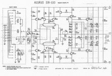
Are you Aware of exactly What a DIA 100 sounds like?
Heavy Bass and Ear punishing shrillness.
Very unpleasant when I auditioned one.. when they were first released. Surprisingly so from a reputable Brand name.
There was a Revised version released Very soon after, as the DIA proved unsaleable.
Dunno how you could Fix it's sound performances though.
Likely simpler to just buy a better amp.
Unlikely the DIA is worth 50$ even when working well.
- Status
- This old topic is closed. If you want to reopen this topic, contact a moderator using the "Report Post" button.
- Home
- Amplifiers
- Solid State
- Need advice for upgrading an Acurus DIA-100 amp