Khron said:
That's the 10 ohm // output inductor.
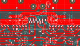
Ah, I didn't see a Zobel so I didn't consider the output inductor. Will there be a Zobel? As I recall there has been some discussion in a thread or two about locating the Zobel as close to the outputs as possible. The output inductor//resistor could be located off the main board to save space (bigger coil).
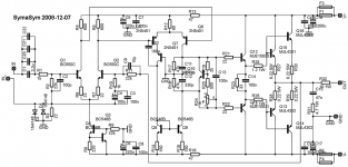
Also, many of the amps you see can be built with different devices. I remember you asked me before on my patchwork thread if it could be built with more common transistors. It's nice to have the best choice for every part but it's not critical. I'm sure the symasym wouldn't suffer a performance hit if you changed the outputs or used a different differential pair. Don't be afraid to experiment.
The Zobel is on the right side of the "bias generator" group, in the middle of the board.
Mike Bittner mentions on the Symasym page some of the modifications possible and/or necessary (2sa/2sc devices, and different diff pair etc).
I'd rather do one thing right (or at least "right") from the first try, than fiddle around endlessly with possibilities") That's how my whole audio project got dragged through time, now reaching about 3 years without having almost anything done 100%
That's how my whole audio project got dragged through time, now reaching about 3 years without having almost anything done 100% 
Mike Bittner mentions on the Symasym page some of the modifications possible and/or necessary (2sa/2sc devices, and different diff pair etc).
I'd rather do one thing right (or at least "right") from the first try, than fiddle around endlessly with possibilities
That's how my whole audio project got dragged through time, now reaching about 3 years without having almost anything done 100% 
Khron said:The Zobel is on the right side of the "bias generator" group, in the middle of the board.
What can I say - I'm blind
Or is it that colour scheme in Eagle...
Anyway, now that I've actually opened my eyes and looked at it, it looks good. The parts are all well organized, especially in the front end.
 Well, at least at this quite minor stuff

- Status
- This old topic is closed. If you want to reopen this topic, contact a moderator using the "Report Post" button.
- Home
- Amplifiers
- Solid State
- Symasym PCB