jam said:read Japanese
Jam,
maybe you should try it sometime.
Carefully though, a relative of mine lost his head on a samoerai sashimi blade in that place.
Attachments
I shall do so, but I'm not sure how much good it will do me since I can't get the parts. Still, it is one step in the right directionRoar Malmin said:Weather you have become a person not to be helped, I do not know. I have, however, noticed the fact that if you help people out, you wil not be helped when in dire straits.
You can send me a private mail, I have the complete schematic.
Regards
Roar
Ever had one of those weeks where everything you touch turns to ****? This is one of those weeks. Sorry to sound desperate.jacco vermeulen said:www.earsp.site40.net
UN07/UP07 are 250mW JFETs, complementary replacements are (selected) J103/K246.
A few other brands used the UN/UP devices.
(EW needs a hug and a Xmas present)
The UN07 and UP07, when removed from the circuit, test as a JFET, not a MOSFET. And, even if the mini-schematic in the downloaded PDF shows a phono stage, both the phono stage and the main amp stage use these devices as the final output stage, which lends to the suggestion that they are JFET's.
Do a diode test of one with a multimeter...ought to test as a JFET.Roar Malmin said:Jacco, I must take exception to your claim. They are MOSFETs, and not JFETs. I happen to have some of them. Furthermore, they are in a TO-126 package, whereas the 2SK246 use a TO-92 package.
Regards
Roar
In another thread I found somewhere online, someone was also looking for these devices and found Addison Electronique...seems they had zero stock of these. I may contact them and see if that's still the case.lineup said:https://www.addison-electronique.com/catalog/product_info.php?products_id=74876
https://www.addison-electronique.com/catalog/product_info.php?products_id=74877
$0.99 each for UN07D and UP07D
But no description.
Well, this one is back on the bench. I'm tired of looking at it.
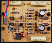
Before I go tearing into it, replacing parts, I wanted to get some feedback. I took voltage measurements all across the board to see what was happening, and here are the results:
You can see that the top board (L chan) is working correctly, and the offset at the output is at about 280mV. The bottom board (R chan), is currently passing a signal (which it did not do the last time I had it on the bench), but you can see the offset is at -3.2V, due to the -3.5V at the gates of the output pairs. Since the voltages on Q205 and Q207 appear to be pretty decent, does it make sense that the likely root cause is Q206?
(FWIW, the right side of R010 connects to the junction of R207 and R208)
I don't work with FET's too often, so the feedback from ya'all is greatly appreciated. Thanks!
Before I go tearing into it, replacing parts, I wanted to get some feedback. I took voltage measurements all across the board to see what was happening, and here are the results:
An externally hosted image should be here but it was not working when we last tested it.
You can see that the top board (L chan) is working correctly, and the offset at the output is at about 280mV. The bottom board (R chan), is currently passing a signal (which it did not do the last time I had it on the bench), but you can see the offset is at -3.2V, due to the -3.5V at the gates of the output pairs. Since the voltages on Q205 and Q207 appear to be pretty decent, does it make sense that the likely root cause is Q206?
(FWIW, the right side of R010 connects to the junction of R207 and R208)
I don't work with FET's too often, so the feedback from ya'all is greatly appreciated. Thanks!
Its more of a puzzle that it may first appear. All of the transistors are working as expected, with the -.3v on the - input. The real question is why its balancing at .3V difference on the input. The output should be at the negative rail, however the - input is at the correct voltage for the output voltage (given a 10:1 divider on the feedback). Q206 is a cascode and seems unlikely to affect anything here. Its working or you would see the equivalent of an open circuit. Further if a signal comes out it must go through. This is a single ended amp internally.
If you pass a signal what happens? What voltages does it clip at? If you swap the input pair does the offset flop? Its possible that the + input transistor is damaged.
If you pass a signal what happens? What voltages does it clip at? If you swap the input pair does the offset flop? Its possible that the + input transistor is damaged.
Stax preamp i/f for CP-Y cartridge
Hello
I have a Stax CP-Y cartridge with ECP-1, but no schematics. Does anyone have this, or for example the mentioned preamp schematics to share? (I am going to drop Roar Malmin a message as well")
Regds
Rolv-Karsten
Weather you have become a person not to be helped, I do not know. I have, however, noticed the fact that if you help people out, you wil not be helped when in dire straits.
You can send me a private mail, I have the complete schematic.
Regards
Roar
Hello
I have a Stax CP-Y cartridge with ECP-1, but no schematics. Does anyone have this, or for example the mentioned preamp schematics to share? (I am going to drop Roar Malmin a message as well
Regds
Rolv-Karsten
Weather you have become a person not to be helped, I do not know. I have, however, noticed the fact that if you help people out, you wil not be helped when in dire straits.
You can send me a private mail, I have the complete schematic.
Regards
Roar
Hi Roar, I recenyly managed to buy a pre Stax CA-Y, I wasn't so luky to find a CA-X, and since there is so little regarding both pre on internet I noticed that you have the schematics of the X. As far as I can understand the two pre are rather similar, with all respect, missing the Y the split between the channels and the separate power supply.
Now I wonder if you also have schematics of the Y, and if you don't if you can share the schematic and manual of the X. I'm prepared of course to pay what is necessary.
Hoping to hear from you soon
Bob
Hi QUADESL63,
thank you for offering your help.
As you have read I bought a Stax CA-Y in US a few months ago. At first I used it for short time spans and the sound was perfect. At Xmas during a long playing session lasted 3 hours suddenly the pre started to emit bangs and bursts so loud that I feared for my speakers and the sound deteriorated sharply. Now it still play badly and I can't augment the volume.
I'm not a technician and certainly I'll take it to a shop for repair but considering the construction complexity of the item it would be helpfull to supply the shop a diagram. A managed so far to obtain the diagram of the CA-X but a specific one would be better.
I don't think that with so very little information you could have an idea of what could have gone wrong (capacitors?), but if you do please tell me.
Happy new year.
Bob
- Status
- This old topic is closed. If you want to reopen this topic, contact a moderator using the "Report Post" button.
- Home
- Amplifiers
- Solid State
- Stax CA-X Preamp