Tks Danny. Great input and ideas and info.
1) yes the thermal pad will go, will replace with the silicone pads I have on order.
2) On the predrivers, Can I lift them from the pcb and install on the main heatsink with ptp wiring? Would invalidate the clone warranty")
After placement on the main pcb, I do plan on reverting to the 36 ohm resistors. If that works, then I might line up and install an aluminum buss across all the TO220's. Better conduction/ heatsink contact, as well as the bus itself acting as a heatsink.
Will play with r9/10 as well.
3) Question. How do I adjust output stage bias?
1) yes the thermal pad will go, will replace with the silicone pads I have on order.
2) On the predrivers, Can I lift them from the pcb and install on the main heatsink with ptp wiring? Would invalidate the clone warranty
After placement on the main pcb, I do plan on reverting to the 36 ohm resistors. If that works, then I might line up and install an aluminum buss across all the TO220's. Better conduction/ heatsink contact, as well as the bus itself acting as a heatsink.
Will play with r9/10 as well.
3) Question. How do I adjust output stage bias?
Last edited:
You can try to install the predrivers also in the heatsink, see if you can reconnect the predriver not at the original holes but closer to the heatsink to keep minimal wire length. Maybe also move some resistors.
Output stage bias is done with the base stoppers R23/R24: 27ohm=180ma, 22ohm=200ma, lower=more current.
Also by changing the drivers current, R19/R20, but those drivers are already highly biassed.
Another tweak, the input stage uses a single 15v zener, better to use a string of 4.7v+4.7v+5.1v zeners.
Zeners above 6v can be much more noisier.
Changing R9/R10 from 360 to 470 gives the driver stage 6db lower distortion, according to Ltspice
Last edited:
Tks Gaborbela, sounds logical, but how should I trim it? I'd rather it do 5 watts class A instead of 20 given that this version I am building is in a smallish enclosure. I'd rather not have to install fans
Now I understand what you mean, I was not aware there is no trimmer pot to set up the bias.
Only option you have you must change some resistor values like the 100K (R3,R4) or the 3.3K (R5,R6). To do any change you must run some sim. The other option you got to lower the rail voltage, that automatically lower the total bias. Danny has a lot of experience with these amp, I do not even own one so I can give only some limited advise based on the circuit.
I think he can help you much more, he simulated the amp and he did a lot of real life tests also.
Hi,
Just a thought: perhaps the reason DartZeel sounds as good as people say is because: a) No global feedback, but: b) internal loop feedback across the two amplifying BJTs, and c) emitter follower driver across all three stages. Using the emitter followers will of course help make the amp fast.
So here are some ideas on how to take these insights and play:
1) Replace output with MOSFET to simplify signal path. The VAS section should be modified with a BIAS pot. And of using 2sk1058/2SJ162 we would need two of each.
2) Use the DartZeel idea of local loop feedback to drive MOSFETs with say 6SN7s coupled as a plate follower.
Thoughts?
D.
Hi,
Just a thought: perhaps the reason DartZeel sounds as good as people say is because: a) No global feedback, but: b) internal loop feedback across the two amplifying BJTs, and c) emitter follower driver across all three stages. Using the emitter followers will of course help make the amp fast.
So here are some ideas on how to take these insights and play:
1) Replace output with MOSFET to simplify signal path. The VAS section should be modified with a BIAS pot. And of using 2sk1058/2SJ162 we would need two of each.
2) Use the DartZeel idea of local loop feedback to drive MOSFETs with say 6SN7s coupled as a plate follower.
Thoughts?
D.
I agree with you
Great idea, I would use some high power laterals from Exicon one or two pair per channel to get out some power or capability to drive any speakers.
I would keep the driver stage as it is with the bipolars and the mentioned tube input stage. Something like the Moskido amp was only with with a single tube.
Attachments
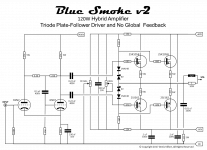
Hybrid MOSFET DartZeel?
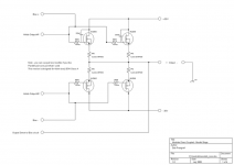
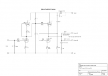
Here is what I have tried so far: the Blue Smoke v2.
This is a simple grounded cathode as the first stage and plate-based feedback on the second stage. So nothing new here. What is nice is that the plate follower circuit throttles back the amplification factor of the cascaded triodes (which we don't need as it would be 10X X 10X = 100 and we want circa 20X) and trades it for lower output impedance of the second triode. This helps drive the gates of the MOSFETs. So good bass and faster rise time.
I have built this circuit and it sounds quite nice. Carbon comp resistors on the plates gives you that "triode sound" and the MOSFETs give you the current drive so we can drive modern speakers.
The major difference between the DartZeel approach and the Blue Smoke v2 is that the DartZeel's loop feedback goes from the collector to the emitter of the first amplifying transistor. DartZeel's feedback is thus looped around TWO measures of amplification. The plate follower feedback arrangement is only around the last triode.
We could get closer to the DartZeel concept by cascading two triodes. Then feed the signal from the plate of the second triode to the cathode of the first. That I have not built - but it would be worth a try.
Attachments
Yes - this thread may have taken an odd turn. I just get a little suspicious of the claim "Never Heard Before". Looking at the DartZeel circuit, it has one input amplifier stage. Then the VAS. Followed by the cascaded emitter follower output stage. The output stage is not included in the loop feedback - but the first two stages are. Then the circuit is PNP/PNP mirrored (which was done by Hafler in the 80'ies). So yes, a simple design - but nothing spectacular. And as such one can observe some of the same rules playing with MOSFETs and tubes.
It is unusual in the use of a diamond buffer output stage. You convert this to emitter/source followers and it is a different circuit altogether. Apparently this is hard to comprehend
Really not aware that Hafler ever used a diamond buffer output. Which model would that be?
The absence of loop feedback around a conventional follower output stage is not exceptional. Lots of mainstream manufacturers do it: NAD and Krell readily come to mind.
Really not aware that Hafler ever used a diamond buffer output. Which model would that be?
The absence of loop feedback around a conventional follower output stage is not exceptional. Lots of mainstream manufacturers do it: NAD and Krell readily come to mind.
Yes - the feedback/no feedback discussion is always interesting. Not having global feedback frees up the amp from trying to compensate for the speakers back EMF.
About the Hafler comment: I was not referring to Hafler using a diamond buffer. I was pointing out that they used PNP/PNP mirroring of the input and VAS stage as well as the emitter followers that drive the MOSFETs. Which is also quite common.
So I think it would be easy to rig the PNP/NPN input and VAS stage to use MOSFET outputs
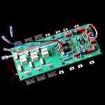
I recently finished one of these amplifies using the claimed "1:1" copy pcb boards. They are fairly easy to build, probably one of the easiest amplifiers I attempted to put together. These sound fantastic, probably one of the best chinese copy cat offerings. I dont know how the other versions sound but this one is definitely worth building.
An externally hosted image should be here but it was not working when we last tested it.image hosting 5mb
Hi Apoopoo999, I have the same inrush limiter circuit as you have in the photo. I am struggling with the implementation...
The on-off connector is separate from the main on-off that the circuit needs to power up, so by default u need 2 power switches.
You cannot pre-short the on/off connector so as just to use the main power switch to turn the amp on/ off... you physically have to manually first turn main power on, then after 1-2 seconds short the on/off jumper, this is a 2 step manual process just to switch the amplifier on.
Lastly, removing the short from the on/off jumper does not turn the amplifier off... it stays on, so you then need to use the mains switch to turn the amplifier off.
It seems the on/off jumper "only" turns the amp on, removing the short does not turn the amplifier off... this is weird. To turn the amplifier off (without using mains switch) you need to short the 75c jumpers, But that too is not feasible since to turn power back on, you need to recycle the mains switch again... this is a pain. Why did they design it this way... unless I have a defective board...
How does yours work?
Hello,
I awaken this thread because after months passed to buy everything I needed, I finally completed this magnificent amp.
I was already convinced that it could sound very good, but the delicate detail, the seductive timbre, the incredible talent in giving back with a disarming naturalness even the most complex musical plots, really makes this amp one of the best things ever heard in more than thirty years of passion.
Absolutely recommended.
I awaken this thread because after months passed to buy everything I needed, I finally completed this magnificent amp.
I was already convinced that it could sound very good, but the delicate detail, the seductive timbre, the incredible talent in giving back with a disarming naturalness even the most complex musical plots,
really makes this amp one of the best things ever heard in more than thirty years of passion.Absolutely recommended.
An externally hosted image should be here but it was not working when we last tested it.
An externally hosted image should be here but it was not working when we last tested it.
An externally hosted image should be here but it was not working when we last tested it.
Hello,
I awaken this thread because after months passed to buy everything I needed, I finally completed this magnificent amp.
I was already convinced that it could sound very good, but the delicate detail, the seductive timbre, the incredible talent in giving back with a disarming naturalness even the most complex musical plots,
Absolutely recommended.
An externally hosted image should be here but it was not working when we last tested it.
An externally hosted image should be here but it was not working when we last tested it.
An externally hosted image should be here but it was not working when we last tested it.
Nice amp you got there. Enjoy it. Are you using DC servo? What is the rail Voltage using one pair power transistors?
I want to build these with the 3 pair power transistor, unfortunately, I am no longer able to log in to my Taobao account (I am unable to receive a text message) only has a home phone. If someone has an extra set PC board for sale I would be interested to buy it, or if you want to order I would love to join with you to order together. 【終極蕭王】3並單聲道後級功放板 控制力一流(8歐200w) Thanks
Thanks!!
DC servo cards a real disappointment!!
After trying the finale for a week, I put them together but the general musicality (dynamic, soundstage, speed, etc.) was much more dull and withering.
Remove after two days and throw away. I kept the 40 mV DC offsets on one channel and about 85 mV on the other, but what's important was that the circumstance didn't create any kind of problem for both listening and all the speakers tested.
I do not agree at all with the idea of assembling more than one pair of complementary amps, because apart from the fact that not even one extra Watt of power is available, this would frustrate one of the precise requirements of the original project and its designer d’Hervé Delétraz:
1. No general negative feedback,
2. Open loop input and output stages,
3. No contact devices (selector, relay, fuse, etc.) over the entire signal path,
4. Only six transistors per polarity branch, from input to output,
5. A single pair of bipolar output transistors.
I chose a single 600VA transformer and two 40Vac outputs to power it, which become about 55 Vdc straightened and I can also drive my MAGNEPAN 1.6 wonderfully.
Last edited:
These versions use multiple power transistors for more power.
Same concept (schematics) with multiple power transistors. I did read it somewhere
聲儒音響 極致的藝術空間
I have two 600VA 39-0-39V transformer for monoblocks
I registered with Taobao last year, for a while I did not log in and now I want to log in they text me some security code. I only have a home phone, cannot get their text message and unable login, it makes me so upset.
What is your bias setting/channel because of that high rail voltage for one pair power transistor? (I think) Can you drive 4Ohms speakers?
Thank you
3. No contact devices (selector, relay, fuse, etc.) over the entire signal path,
Did you attempt to recreate a protection circuit similar to the one used in the original?
These versions use multiple power transistors for more power.
Same concept (schematics) with multiple power transistors.
This will change the sound character a lot. And will necessitate the inclusion of emitter resistors...
This will change the sound character a lot. And will necessitate the inclusion of emitter resistors...
Of course, please see the picture
Attachments
- Home
- Amplifiers
- Solid State
- Dartzeel amp schematic - build this?