I'm wondering how to properly integrate a servo in a classical "one opamp" balanced line receiver. Is the schematic attached the proper way to do it ?
I'm a bit surprised to not find anything about this by searching this forum. CDPs output stages after a balanced output DAC often use coupling caps for example
I'm a bit surprised to not find anything about this by searching this forum. CDPs output stages after a balanced output DAC often use coupling caps for example
Attachments
Thanks for the comment
Actually, from what I saw on the THAT website, they're either using a way more complicated four-opamps system (high performance solution) or simpler one-opamp receiver. They are not servoed at first sight. But they certainly look interesting (very nice thd and rejection figures).
In this case however I want to use a discrete amplifer as U1 and an opa134 or opa227 for U2.
Btw, this is not the receiver described in the Walt Jung opamp applications book: http://books.google.be/books?id=dunqt1rt4sAC&pg=RA6-PA454
I should have paid more attention to your schematic the first time. If you have drawn this as you intended you are only amplifying the differences in your input. This is not a conventional balanced line receiver. Since your Vin's are different you will have a signal, but you will have no low frequencies (because of C1).
It is also possible that I am confused about exactly what you are trying to do.
It is also possible that I am confused about exactly what you are trying to do.
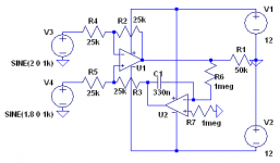
In the schematic :
U1 + R2/R3/R4/R45 is the usual difference amplifier.
R1 is the load
V3/V4 are the input voltages, with different DC offsets (2 and 1.8VDC). On the schematic, ac signal is at 0v/1khz
U2+R6/R7/C1 is the servo.
In simulator at least, 20hz signals are not attenuated. The servo controls the the usually grounded leg of R3 and feeds there a DC offset to balance the offsets at the input.
What I had in mind was to guarantee 0v offset at the output of the receiver, despite varying offsets at the inputs, instead of just a trimmer. Sorry I wasn't clear.
My mistake was in thinking the 1.8V and 2V were the AC signal in with 0 DC offset. It did not make sense that they were in phase and would cancel with only the .2V to be amplified. Now that your explanation has cleared that up, yes this is one of the ways to servo out the DC. It will also remove low frequencies just like a cap in the output. At what point this happens depends on the cap value and the impedances around it.
You have shown the amp (U1) as unity gain. I assume this is what you intended. Still, with positive feedback at low frequencies you may have a problem with oscillation. You can avoid this problem by making U2 non inverting and routing the output to the inverting input of U1.
You have shown the amp (U1) as unity gain. I assume this is what you intended. Still, with positive feedback at low frequencies you may have a problem with oscillation. You can avoid this problem by making U2 non inverting and routing the output to the inverting input of U1.
- Status
- This old topic is closed. If you want to reopen this topic, contact a moderator using the "Report Post" button.