HI Anybody else built or had experiance this amplifier with the ThermalTrak Transistors ??
I have just completed 2 of these 200Watt LD amplifier modules (Jaycar kits) i have one problem, even with the 47om resister in Q7s emitter i cannot get anywhere near 7-10mV across any of the .1ohm emitter resisters mine all read around 2.5mV. with 30mv across the speaker terminals, (Rail voltage is +55.8 , 0 , -55.8.
The voltage acros the diodes (Q10 & Q11 base) is OK at 2.28Volts. All other circuit
voltages read Fine as per the article , & the modules seem to work OK, (listening as im am writing this ) sounds pretty good !!!!
both modules are exactly the same , so what am i missing here??
Are there any updates to this article??
Component variation problem?? or what
Thanks Mick Hawtin
7-10 mV gives 70-100mA, which is normal
The diodes should create a higher voltage, the more current.
1. You can increase current in Q7, Q9. But not too much, cause they may overheat.
54V x VAS-current = power dissipation in those TO126, BF469/470.
With good cooling maybe we can use 2 Watt for those TO-126
2. A slight effect you could get from reducing BASE resistors of MJE15030/31 to 47 Ohm. (from 100Ohm)
3. Reduce current in drivers a bit will lower the voltage drop in drivers.
= increase EMITTER resistors of MJE15030/31, from 100 Ohm to 220 Ohm.
4. Parallel each 0.1 Ohm emitter, with another 0.1 Ohm, will double the current:
3.5 - 5 mV for ame 70-100 mA
-------------------------------------
These adjustments can all effect the operation of the amplifier.
How little or much is hard to say.
Here are some topics about use of Thermal-Trak.
With posts by clever amplifier designers like Bob Cordell & Douglas Self !!!!!!
Biasing/thermal compensation of Thermal Trak transistors
http://www.diyaudio.com/forums/showthread.php?threadid=105934
On Semi ThermalTrak
http://www.diyaudio.com/forums/showthread.php?threadid=71534
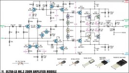
Below is the schematic of this Ultra-LD 200w amplifier
The diodes should create a higher voltage, the more current.
1. You can increase current in Q7, Q9. But not too much, cause they may overheat.
54V x VAS-current = power dissipation in those TO126, BF469/470.
With good cooling maybe we can use 2 Watt for those TO-126
2. A slight effect you could get from reducing BASE resistors of MJE15030/31 to 47 Ohm. (from 100Ohm)
3. Reduce current in drivers a bit will lower the voltage drop in drivers.
= increase EMITTER resistors of MJE15030/31, from 100 Ohm to 220 Ohm.
4. Parallel each 0.1 Ohm emitter, with another 0.1 Ohm, will double the current:
3.5 - 5 mV for ame 70-100 mA
-------------------------------------
These adjustments can all effect the operation of the amplifier.
How little or much is hard to say.
Here are some topics about use of Thermal-Trak.
With posts by clever amplifier designers like Bob Cordell & Douglas Self !!!!!!
Biasing/thermal compensation of Thermal Trak transistors
http://www.diyaudio.com/forums/showthread.php?threadid=105934
On Semi ThermalTrak
http://www.diyaudio.com/forums/showthread.php?threadid=71534
Below is the schematic of this Ultra-LD 200w amplifier
Attachments
")
200Watt LD Amp
Thanks for every ones feedback on this Amp problem , i actually contacted one of the designers , John Clarke who came to the same conclusion that you guys did,
that is ,the fixed resistor in series with the diode string to increase the quiescent
current in the output stage, i finally ended up with a 7.5ohm series resistor for
8.5mV across the emitters = 85ma .
Amp running fine now , very stable , hopfully this will help some other builders who
may have the same problem.
Regards Mick
mickyh said:HI Anybody else built or had experiance this amplifier with the ThermalTrak Transistors ??
I have just completed 2 of these 200Watt LD amplifier modules (Jaycar kits) i have one problem, even with the 47om resister in Q7s emitter i cannot get anywhere near 7-10mV across any of the .1ohm emitter resisters mine all read around 2.5mV. with 30mv across the speaker terminals, (Rail voltage is +55.8 , 0 , -55.8.
The voltage acros the diodes (Q10 & Q11 base) is OK at 2.28Volts. All other circuit
voltages read Fine as per the article , & the modules seem to work OK, (listening as im am writing this ) sounds pretty good !!!!
both modules are exactly the same , so what am i missing here??
Are there any updates to this article??
Component variation problem?? or what
Thanks Mick Hawtin
Hello Mick, my solution to the quest for emitter voltage was to place a trim pot in series with the diodes, on the board near Q 12, cut track and solder directly. After going through D Self's distortion notes on his website I also picked both ends of the 100R emitter resistors on Q10 and Q11, removed them from the SP output rail and joined them together, palcing a 1uf cap across these two resistors(from emitter to emitter) also decreases crossover distorion. on the second amp I removed both reistors and placed a 220R on the board close to q10&11 with a 1uf cap across it. this mod lifts a veil espceially in the mid and upper ferquencies. I was drawn to this fix and Self's site because someone mention it was a derivation of Self's blamess amp. He also suggested getting rid of the tail resistor in the LTP, I asked him why? he told me that it causes problems on power up when you use a variac. So I don't see any reason so far to remove it.
Hope this works for you.
By the way I blew up Q9 and was forced to replae it with a BF459, higher Ft but also higher Cob, the difference between channels is noticable, the BF469 with 1.8pf is better, this it mentioned in the book by Randy Slone.
By alfred - I was drawn to this fix and Self's site because someone mention it was a derivation of Self's blamess amp. He also suggested getting rid of the tail resistor in the LTP, I asked him why? he told me that it causes problems on power up when you use a variac. So I don't see any reason so far to remove it.
Ran into small issues with my blameless design.. same as this
(almost..led CCS) get rid of the 6.8k 1W(jumper), Q5 Re=300R,
Q7 Re=100R... You will get less turn on noise, cooler running
VAS
and a little more open loop gain. (1.8ma LTP/ 6.5ma VAS)this was measured on the real thing ,not sim.By the way I blew up Q9
BTW, a good stable design (ran it for a month before moving
on to new design)..
OS
The ULD Mk2 seems quite good. The second part of the blurb covered various things mentioned here. On a group buy these modules are around $AU50, $US33. Quite good value. Would any one like to offer advise on the following.
The amp uses Four thermalTraks while the manufacturers info shows six devices, probably why Leo and John ended up having to add resistance to the temp diodes. What happens if we put the other two back in.
Any thoughts on getting rid of the NP electrolytic input cap
Any other mods without changing the board layout.
Thanks
pheonix358 said:The ULD Mk2 seems quite good. The second part of the blurb covered various things mentioned here. On a group buy these modules are around $AU50, $US33. Quite good value. Would any one like to offer advise on the following.
The amp uses Four thermalTraks while the manufacturers info shows six devices, probably why Leo and John ended up having to add resistance to the temp diodes. What happens if we put the other two back in.
Any thoughts on getting rid of the NP electrolytic input cap
Any other mods without changing the board layout.
Thanks
I would like ot know how to get them for $50?
I believe adding two other output devices would require some extraneous wires if you don't object to that and the possible side effects, it is perfectly amenable.
My habit is to replace all electro input caps with stacked polyester(1uf), probably because I have some in the cupboard, electros have a little hysterisis, sluggish in LF and poor mid and high freq quality/response, despite the fact that eclectros are getting beter over time.
Please refer to post 7+8, however this requires a little surgery on the board.
refer to other links
http://www.diyaudio.com/forums/showthread.php?postid=1650894#post1650894
http://www.diyaudio.com/forums/showthread.php?postid=1651523#post1651523
alfred
alfredrofe said:I would like ot know how to get them for $50?
Hi Alfred,
From Electus Distribution:
Amp module:
Qty 1+ $57.57 (GST not included) Qty 3+ $53.07 Qty 5+ $48.57
PSU:
Qty 1+ $35.17 (GST not included) Qty 3+ $32.42 Qty 5+ $29.67
regards
AKSA said:For best results on this and any amplifier input cap, use teflon.
More expensive than the rest of the components put together, but astonishingly natural sound, absolutely no coloration.
Cheers,
Hugh
Hello Hugh,
In previous corespondances you indicated that HiFi is a luxury, I now see evidence of extravagent luxury, one passive component worth more than or equal to an entire kit. ($50 to $90) out of my league I am afraid. Even if I asked Mrs Rumpole the answer would be I can get shoes of course. When we met I clearly only remember to feet how it morphs into millipede status is a mystery. I guess that why us blokes like electronics and motor vehicles, the path to our goals is time and money. far more easy to understand.
I wish you and your Mrs Rumpole the best for the silly season, be safe and try not to pine for your babies in the antipodes.
To all DIY Audio contributors best wishes for 09 and thank-you all for your generous contributions, this is truly an oasis in the greater scheme of life for satisfying our thrist for knowledge on the path to our individual audio quests.
Alfred
Re: Silicon Chip 200Watt LD amplifier
Hello SandyK, this produces an extraordinary more refined sound have you got any other gems, please feel free to email direct
alfred
sandyK said:IF the LTP devices are well matched, try fitting a 130R 1% MF resistor in place of the 0 ohm link between Q2 collector and Q3 and Q4 bases in both channels. Have a listen before and after.
SandyK
Hello SandyK, this produces an extraordinary more refined sound have you got any other gems, please feel free to email direct
alfred
Re: Re: Silicon Chip 200Watt LD amplifier
it might be even better to convert the mirror to a Wilson or Widlar type. But, add that extra resistor that is discussed in the mirrors thread.alfredrofe said:
Hello SandyK, this produces an extraordinary more refined sound have you got any other gems, please feel free to email direct
alfred
Silicon Chip 200Watt LD amplifier
alfredrofe
The quoted 130 ohm MF was only an estimate.
If the LTP resistors are well matched, you could try fitting a 200ohm trimpot there instead, and adjusting the trimpot to get as close as possible to 0mV between the collectors of the LTP when the amp is warmed up. My preferred method with this design would have been to use a 200ohm trimpot and a 1N5819 Schottky diode in series, (to give thermal tracking) but the physical layout of this amplifier makes that awkward.
As Andrew says, this subject was thrashed out in the Mirrors thread. Fortunately, a few people like Ostripper did try to obtain this closer balance, and now strive for better balance of the currents in both sides of the LTP in their simulations too.
SandyK
Re: Silicon Chip 200Watt LD amplifier
In reference to the thermal tracking are you suggesting the diode should be placed on the heatsink? furthermore the proximity of the additional components and their sensitive nature in the circuit may make this inadvisable? please comment.
Alfred

sandyK said:alfredrofe
The quoted 130 ohm MF was only an estimate.
If the LTP resistors are well matched, you could try fitting a 200ohm trimpot there instead, and adjusting the trimpot to get as close as possible to 0mV between the collectors of the LTP when the amp is warmed up. My preferred method with this design would have been to use a 200ohm trimpot and a 1N5819 Schottky diode in series, (to give thermal tracking) but the physical layout of this amplifier makes that awkward.
SandyK
In reference to the thermal tracking are you suggesting the diode should be placed on the heatsink? furthermore the proximity of the additional components and their sensitive nature in the circuit may make this inadvisable? please comment.
Alfred
Silicon Chip 200Watt LD amplifi
Alfred
Just mount the diode vertically in the general area of the LTP, or in this case,where you already have fitted the 130ohm resistor.
Why not just try it initially with a 200 ohm trimpot where the resistor now is?
Set it initially to 130 ohms. This series resistor will reduce the current through Q2 collector to that of the collector current of Q1, which has been robbed of a very small amount of current by the bias requirements of the next stage. (Q8)
SandyK
Hi all.
I want to add an extra thermaltrak each side. I am thinking of positioning them above and to the centre of the existing pair. This makes wriring simple with very small leads. The extra diode should obviate the need for a resister in this part of the circuit. Any other changes anyone would recommend and do I need any other changes.
Thanks in advance
Terry
- Status
- This old topic is closed. If you want to reopen this topic, contact a moderator using the "Report Post" button.
- Home
- Amplifiers
- Solid State
- Silicon Chip 200Watt LD amplifier