OK, I know this has been covered again and again. I have read threads regarding this subject many times over. Nonetheless, I need to make sure I have a firm grasp of this subject before I continue experimenting.
I see two fundamental problems with this topology. I need the gurus to tell me if I've got it.
1) There will likely be a "balance" issue between complementary halves of the input stage. A circuit needs to be included to keep them balanced. If not included, I would anticipate one half riding the rail and the other doing all the work. I'm not sure I understand why this isn't a problem with a no current mirrors topology. I'm assuming the current mirrors raise the OL gain causing this to occur.
2) Using a Slone style straight push-pull VAS without a current source won't work because the VAS idle current is completely undefined.
Yes?
Thanks,
John Gedde
jgedde said:OK, I know this has been covered again and again. I have read threads regarding this subject many times over. Nonetheless, I need to make sure I have a firm grasp of this subject before I continue experimenting.
I see two fundamental problems with this topology. I need the gurus to tell me if I've got it.
1) There will likely be a "balance" issue between complementary halves of the input stage. A circuit needs to be included to keep them balanced. If not included, I would anticipate one half riding the rail and the other doing all the work. I'm not sure I understand why this isn't a problem with a no current mirrors topology. I'm assuming the current mirrors raise the OL gain causing this to occur.
2) Using a Slone style straight push-pull VAS without a current source won't work because the VAS idle current is completely undefined.
Yes?
Thanks,
John Gedde
You are correct. A complementary input stage with current mirrors, like Slone, has its idle current undefined if transistor betas go large. There are ways around this to largely have your cake and eat it too. One approach is to return a resistor from the output of the current mirror to a fixed voltage that is the voltage needed to be applied to the VAS input to establish the desired VAS standing current. The fixed voltage source can be made to have the right temperature coefficient to match the input characteristic of the VAS. For example, a Darlinton VAS with a 22 ohm emitter degeneration resistor and a standing current of 10 mA will want a fixed voltage source of about 2 Vbe plus 220 mV below the rail. This is a bit oversimplified, because the Vbe's may not all be the appropriate value due to different current densities, but you get the idea. The added resistor can often be of a fairly large value compared to the size of the load resistor that would be used in a non-current-mirror-loaded input pair.
Another issue of concern with complementary input pairs has to do with transconductance matching. This is a bigger concern with JFETs, where the P-channel and N-channel pairs may not have the same transconductance at the same operating current. Mismatched transconductances can cause increased distortion.
Cheers,
Bob
Thanks Bob. You certainly qualify as a guru!
I'm not sure what you mean about the "output" of the mirror. You mean the "load terminal"? I would expect your suggestion to mean the tied bases of the mirror transistors.
In any case, how about this?
Thanks!
John
I'm not sure what you mean about the "output" of the mirror. You mean the "load terminal"? I would expect your suggestion to mean the tied bases of the mirror transistors.
In any case, how about this?
Thanks!
John
Attachments
Hi
I thought we covered this already?
http://www.diyaudio.com/forums/showthread.php?s=&threadid=118873
http://www.diyaudio.com/forums/showthread.php?postid=1413451#post1413451
BTW, how did the OK180 work out?
Cheers,
Glen
I thought we covered this already?
http://www.diyaudio.com/forums/showthread.php?s=&threadid=118873
http://www.diyaudio.com/forums/showthread.php?postid=1413451#post1413451
BTW, how did the OK180 work out?
Cheers,
Glen
Good question. A question to which I don't have a convincing answer. It is an audio amp.
Because it's there?. The challenge to get the hypercomplex to work? An obsession with measurements? Good old fashioned psychosis? Perhaps all of the above....
I design "out there" electronics for a living in an industry where better is not always the enemy of good enough. $1200 MOSFETs, $200 2N2222As, $400 LM139's and $6000 FPGAs are routine. The design always must outperform specification even when operating under "outside nominal" conditions. On the other hand, cutting edge components are shunned as not having "heritage." The trick is to use old technology to achieve bigger, better, and faster goals.
Gentlemen, we have the technology...
One can never have too much money, a lady too pretty, too much horsepower, or low enough distortion...
John
G.Kleinschmidt said:Hi
I thought we covered this already?
http://www.diyaudio.com/forums/showthread.php?s=&threadid=118873
http://www.diyaudio.com/forums/showthread.php?postid=1413451#post1413451
BTW, how did the OK180 work out?
Cheers,
Glen
Hey Glen! Thanks for chiming in. We did indeed cover this already. I needed confirmation that I truly understood the challenges at hand.
As you can clearly see, your Kleinschmidt 12 was an inspiration. The OK180 is still an elusive goal unfortunately. You're looking at "son of OK180."
I'd love to hear more about the K12. How did it sound? Did it perform as well as you expected or hoped? How's that Land Rover coming along?
I see you've changed your avatar... Where's Rachel?
Cheers,
John
maybe my simmed "solution" will help you see if you've understood the issue:
"optoisolator VAS bias for Comp Diff?"
http://www.diyaudio.com/forums/showthread.php?s=&threadid=56860
also its hard to tell which thread by the default link #, have you seen:
"Unstable VAS current in amp from Slone book"
http://www.diyaudio.com/forums/showthread.php?s=&threadid=56860
"optoisolator VAS bias for Comp Diff?"
http://www.diyaudio.com/forums/showthread.php?s=&threadid=56860
also its hard to tell which thread by the default link #, have you seen:
"Unstable VAS current in amp from Slone book"
http://www.diyaudio.com/forums/showthread.php?s=&threadid=56860
as I was saying, the default linking scheme is a little rough - if the thread title were automatically included it would help...
http://www.diyaudio.com/forums/showthread.php?s=&threadid=16796
http://www.diyaudio.com/forums/showthread.php?s=&threadid=16796
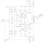
OK. I think I've got it! Distortion at 1 kHz = 0.000056%, distortion at 20 kHz = 0.00012% into 4 ohms. At least that what PSPICE fourier analysis says....
Here's the mystery... In an attempt to define the output of the complementary diff-amps, I added a circuit to servo the supply voltage to one diff-amp to maintain a desired output standing voltage thus defining the VAS standing current (See the current mirror on the upper input stage). It seems the circuit only needs to be on one of the two complementary input stages - the other one follows. If I add another circuit to the so that both stages are constrained, then the distortion increases by an order of magnitude. ?????
I developed the circuit below with the servo because I found that forcing current mirrors by coercing the output to be some fixed voltage causes an imbalance in the diffamp that negates much of what's gained by use of current mirrors in the complementary input stages.
So, I need advice on the following:
1) Is it expected that the non-constrained input stage output always track the constained one or is this a simulation behavior that won't be even remotely true in real life?
2) How should I compensate this beast?
3) Am I ready to break out the soldering iron?
Attachments
jgedde said:OK. I think I've got it! Distortion at 1 kHz = 0.000056%, distortion at 20 kHz = 0.00012% into 4 ohms. At least that what PSPICE fourier analysis says....
Here's the mystery... In an attempt to define the output of the complementary diff-amps, I added a circuit to servo the supply voltage to one diff-amp to maintain a desired output standing voltage thus defining the VAS standing current (See the current mirror on the upper input stage). It seems the circuit only needs to be on one of the two complementary input stages - the other one follows. If I add another circuit to the so that both stages are constrained, then the distortion increases by an order of magnitude. ?????
I developed the circuit below with the servo because I found that forcing current mirrors by coercing the output to be some fixed voltage causes an imbalance in the diffamp that negates much of what's gained by use of current mirrors in the complementary input stages.
So, I need advice on the following:
1) Is it expected that the non-constrained input stage output always track the constained one or is this a simulation behavior that won't be even remotely true in real life?
2) How should I compensate this beast?
3) Am I ready to break out the soldering iron?
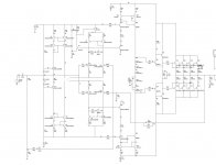
Hi
You are correct that only one LTP/VAS side will need to be servoed (the other side will be steered to match by the gnfb loop).
However your proposed servo doesn't make sense to me.
Attached below is a rather quick mspaint rendition of what I came up with when making my 12W amp. I then abandoned the idea because even without a servo and with 1k load resistors to "constrain" (gain limit - they do not cause any imbalance) the LTP's instead the input stage / VAS distortion was still not dominant over the class A output stage.
Cheers,
Glen
Attachments
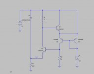
I whipped up a quick simplified version of the mirror "servo" in LTSpice. Here it is...
Basically Q2 sets the current through R1 based on the voltage between the CM output and the rail. Q1 is an emitter follower that sets the supply voltage so as to make the output a diode drop above the reference voltage at the junction of the zener and the resistor. Since the output of the current mirror naturally wants to be at a higher voltage, we only need to servo it down, not up in voltage. That's why this works.
Thanks,
John
Attachments
jgedde said:I whipped up a quick simplified version of the mirror "servo" in LTSpice. Here it is...
Basically Q2 sets the current through R1 based on the voltage between the CM output and the rail. Q1 is an emitter follower that sets the supply voltage so as to make the output a diode drop above the reference voltage at the junction of the zener and the resistor. Since the output of the current mirror naturally wants to be at a higher voltage, we only need to servo it down, not up in voltage. That's why this works.
Thanks,
John
Hi John
I can understand how the servo loop functions, but I can't see how it can work without seriously compromising the function of the current mirror - Q3 (in your subsequent attachment) will be running with minimal Vce. Basically, the voltage across R2 will not begin to drop until Q3 begins to get cut off.
BTW, I had to change my avatar because my new girlfriend was getting jealous, I’m currently fabricating a custom intake manifold to fit a pair of my 45DCOE Weber side draught’s to the Landrover engine and the 12W amp doesn’t sound
 (which is as it should be for a HiFi amp, IMHO).
Cheers,
Glen
G.Kleinschmidt said:I can understand how the servo loop functions, but I can't see how it can work without seriously compromising the function of the current mirror.
Glen
Glen,
What is the best DC servo solution you have seen that does not voltage-error sum at the DIFF input? For a symmetrical diff pair input topology, I have seen circuits which:
1) adjust current sources on input diff pair
2) adjust the voltages to the input cascode pair
3) adjust the the VAS current source pair
I am working with a bipolar version of Nelson Pass Symmetrical diff pair input Super-Sym topology. Symmetrical diff inputs driving + and - output circuits which drive load.
LineSource said:
Glen,
What is the best DC servo solution you have seen that does not voltage-error sum at the DIFF input? For a symmetrical diff pair input topology, I have seen circuits which:
1) adjust current sources on input diff pair
2) adjust the voltages to the input cascode pair
3) adjust the the VAS current source pair
Hi
I think the 'best' option would depend on the specific application. However not to confuse two different things, the servos we are talking about here are for defining/stabilising the VAS current in esoteric fully-symmetrical amps with lots of first stage (LTP) gain.
Such servos do not null out the offset voltage at the speaker terminals caused by Vbe/RE/etc tolerances of the input devices.
Cheers,
Glen
- Status
- This old topic is closed. If you want to reopen this topic, contact a moderator using the "Report Post" button.
- Home
- Amplifiers
- Solid State
- Complementary input stages with current mirrors