It's only now that I look at the circuit diagram of ColinF (linestage only, post #15). As far as I can see it's what I had but with 330k en 1M reversed. Simulation of the circuit with the values of Colin results in a voltage at the output (before cap) of around 5 (where it should be around 15V with a power voltage B+ of 30V).
Not your standard circuit, this one. Took me quite a time puzzling. It's a 3 stage amplifier: normal amplifying stage 1 (1 in circuit), another normal one stage 2 (4 in circuit), ending in a follower stage without amplification (2) with current source (3). A lot of voltage dividing networks to get the mosfets going and and a rather unusual feedback loop from the output back to stage 1 where another voltage divider seems to feedback the signal too (the upper part of this voltage divider could have been going to the B+ like all others, but instead is hung to the midpoint/output.
Anyhow: I'm not an expert in circuits so any explanation is welcomed. And the circuit works both in simulation and in practice. Lastly: I don't think anybody in the world has built this one from scratch on Veroboard (both using bs170 and the very expensive vq1000) except for this nut? Why should you?
I can't remember what I did with it and how it worked out. For me the clue is not in fiddling around with the caps, they ar okay by themselves. The value and type of the 100p can make a difference, I had good result with silver mica caps. Of course you can change the value of this cap to tailor the sound a bit (higher value means slightly rolling off highs at the 20-50 kHz range).
I had the biggest improvements in changing the power supply. Not by just putting another bigger transformer at it, but by trying completely different topologies. Of course you can start with LM317 (just for quick testing the board, not bad at all). In the end I used a Kubota type power supply with mosfet as regulating element. Just google around, you will find a number of beautiful circuits that can be used.
It takes a lot of time and trouble to discover this preamp is very well from itself and not so easy to improve upon. Well, that's no surprise as it is coming from guru Tim de Paracivini himself.
Hi rmgvs,
It's been a while since I last was on diy audio. So you got the line stage going on a board, well done! It's quite possible on the schematic I drew that the 1M and 330k resistors are the other way around. That would make better sense to me to set the output voltage at around 15v. Is your circuit noisy?
Colin.
@ColinF. A year later ....
Is your circuit noisy? Yes it is. No way to solve this issue. It's inherent to the circuit and mosfets as used. So please stop modifying this amp to get rid of the noise. You can modify what you like, do it for fun of or (hoping to get) better sound but don't do it to tame the hiss, it won't work.
Is your circuit noisy? Yes it is. No way to solve this issue. It's inherent to the circuit and mosfets as used. So please stop modifying this amp to get rid of the noise. You can modify what you like, do it for fun of or (hoping to get) better sound but don't do it to tame the hiss, it won't work.
I suspect the main source of noise in this circuit would be the input mosfet. Looking at the data sheet of the BS170 mosfet it isn't specified for noise performance, being designed for low power switching applications. You could parallel the input mosfets, each with their own source resistor (1k with 1 mosfet, 2k each with 2 mosfets, 4k each with 4 mosfets etc). That would cut the noise back but better still, you could replace the input mosfet with a low noise bjt such as 2sc2240. You'd need to change a resistor on the input bias circuit to get it to bias up properly.
One of the lowest noise mosfets out there is the BF862 from NXP - originally designed for AM radio applications. It was measured independently against a whole bunch of other low noise devices about a year ago and it really is absolutely outstanding (noise is under 1nV/root Hz). It is SOT23 SMD, but the results in dealing with it are well worth the effort. Best of all, they are dirt cheap from Mouser.
I used bf862s in an mc headamp. It is a depletion mode jfet, not an enhancement mosfet like a bs170. Still it could work in the 3A circuit. But at 3ma drain current the transconductance is going to be low, about 28mS. I'm not sure what the transconductance of a Bs170 mosfet is at that current, the data sheet only shows that at 200ma and ten times as much. The lower the transconductance the higher the distortion in this circuit. Try a bf 862 and see! It should definitely be quieter. And measure the distortion. An alternative could be a 2sk170gr (or its modern equivalent Lsk170a). Bjts would have low distortion in this circuit. In the 3A phono stage there is an LM394 low noise matched bipolar instead of a mosfet as in the line stage.
This is only just the beginning
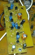
A few years ago (when this thread was running) I even build a version of this preamp with nuvistors for the first two stages (only 2x BS170 at the output).
For the output stage I experimented with 1x BS170 on top with a LM317 as current source. Tried a range of idle currents.
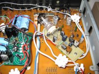
I even designed a special pcb where I could easily switch/choose the different units. I made an arrangement for LM317 stabilized power supply for the unit at the same pcb (worked allright). And a second LM317 for creating the filaments power supply (if I remember correctly 2,5 Volts).
I will check my archive for pictures.
A few years ago (when this thread was running) I even build a version of this preamp with nuvistors for the first two stages (only 2x BS170 at the output).
For the output stage I experimented with 1x BS170 on top with a LM317 as current source. Tried a range of idle currents.
I even designed a special pcb where I could easily switch/choose the different units. I made an arrangement for LM317 stabilized power supply for the unit at the same pcb (worked allright). And a second LM317 for creating the filaments power supply (if I remember correctly 2,5 Volts).
I will check my archive for pictures.
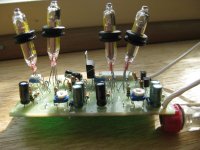
Not a preamp3 anymore!
The hiss problem is solved by this arrangement (or at least greatly diminished). You get a new problem in return: some microphony.
Sound? I'm not sure, was it that much better? Well, I wasn't floored, had expected more of a difference. For me it wasn't good enough, because I went on experimenting.
Next step forward was putting out one stage of amplication and tune the feedback (till no feedback at all). Still I'm not convinced of the superior quality of these pencile tubes.
So I tried the ECC82 in the front (2 stage as in original preamp3). Also have a pcb with that arrangement left in the attic (no pictures made, I could do that).
Then I ended with the 12AU7/ECC82 mosfet stage as described here: link.
This is one of the best souding preamps I have ever experimented with (after this returning to the preamp3 is a problem, so be warned). Smooth and open, nice soundstage etc. So what now? I used a low voltage power supply of around 18V. Idle current of the mosfet around 25mA. Gain is just right at around 5x. Nice for a preamp. But max output is only 0,5V or so for higher impedances. Good amp for low impedance headphones but not ideal as a preamp.
Can be solved by giving the ECC82 a higher voltage. But that means more gain, too much gain that is. So feedback is needed to tame the gain. And in doing this I ended up with a line stage that did not sound as good as the former editions.
And here I stopped and went on with getting a live.
So maybe some other person can take it from here.
BTW: the 12AU7/mosfet preamp: no hiss or hum at all.
Attachments
- Status
- This old topic is closed. If you want to reopen this topic, contact a moderator using the "Report Post" button.
- Home
- Amplifiers
- Solid State
- Musical Fidelity 3A Pre-amp background hiss